

Single-liquid screw valve
A screw valve, single-liquid technology, which is applied to the device for coating liquid on the surface, pretreatment surface, chemical instrument and method, etc. problem, to achieve the effect of quick and smooth response, high man-machine efficiency, and improved efficiency
- Summary
- Abstract
- Description
- Claims
- Application Information
AI Technical Summary
Problems solved by technology
Method used
Image

Examples
Embodiment Construction
[0028] The technical solutions of the present invention will be further described below in conjunction with the accompanying drawings and through specific implementation methods.
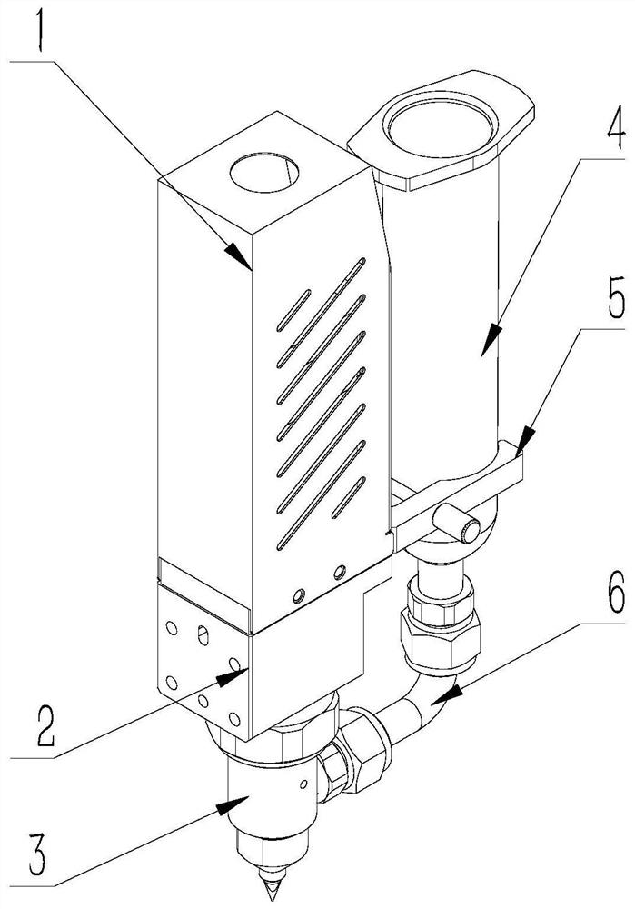
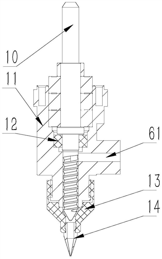
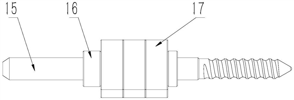
[0029] Such as Figure 1-7 As shown, the embodiment provides a single-liquid screw valve, including a housing 1 , a valve body upper assembly 2 , a valve body assembly 3 , a rubber bucket 4 , a fixing member 5 and a glue delivery assembly 6 . The housing 1 is arranged on the valve body upper assembly 2 , the bottom of the valve body upper assembly 2 is connected with the valve body assembly 3 , and the rubber bucket 4 is fixed on one side of the housing 1 through a fixing member 5 . The glue barrel 4 is connected with the valve body assembly 3 through the glue conveying assembly 6 . The valve body upper assembly 2 includes a fixed seat 9 and a screw assembly 10, the screw assembly 10 is rotatably connected to the fixed seat 9, the fixed seat 9 is provided with a first positioning groove 41, and the...
PUM
 Abstract
Description
Claims
Application Information