Rock mass shearing test system for high-energy accelerator CT scanning

A technology of CT scanning and shearing test, which is applied in the direction of applying stable shearing force to test the strength of materials, instruments, soil materials, etc., and can solve the problem of accurate scanning of rock mass shearing

Active Publication Date: 2021-02-26
INST OF GEOLOGY & GEOPHYSICS CHINESE ACAD OF SCI
View PDF10 Cites 4 Cited by
  • Summary
  • Abstract
  • Description
  • Claims
  • Application Information

AI Technical Summary

Problems solved by technology

[0005] In order to solve the above-mentioned problems in the prior art, that is, in order to solve the problem that the rock mass shear progressive failure process cannot be accurately scanned, the present invention provides a rock mass shear test system for high-energy accelerator CT scanning. The system includes a shear box for accommodating rock mass samples, a bearing device and a shear loading device for supporting the shear box; the shear box includes a static shear box and a dynamic shear box, and the The static shear box is arranged left and right opposite to the dynamic shear box; the static shear box includes a first rectangular frame, and the dynamic shear box includes a second rectangular frame, and the second rectangular frame is connected to the first rectangular frame. The relative setting of the rectangular frame;

Method used


Image

  • Rock mass shearing test system for high-energy accelerator CT scanning
  • Rock mass shearing test system for high-energy accelerator CT scanning

Examples


Embodiment Construction

[0037] Preferred embodiments of the present invention are described below with reference to the accompanying drawings. Those skilled in the art should understand that these embodiments are only used to explain the technical principle of the present invention, and are not intended to limit the protection scope of the present invention.

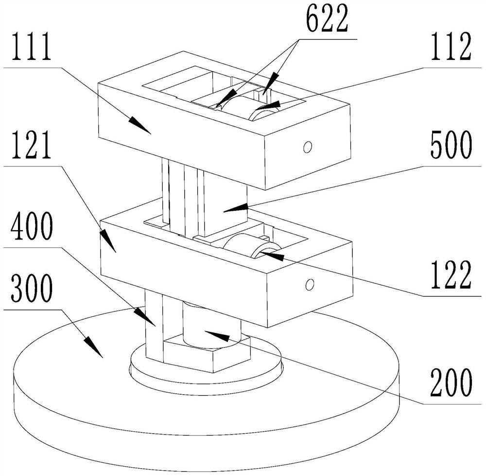
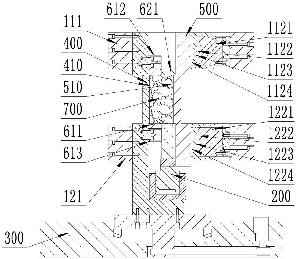
[0038] The invention provides a rock mass shear test system for high-energy accelerator CT scanning, comprising a shear box for accommodating a rock mass sample, a bearing device and a shear loading device for supporting the shear box; The cut box includes a static cut box and a dynamic cut box, and the static cut box and the dynamic cut box are arranged opposite to each other; the static cut box includes a first rectangular frame, the dynamic cut box includes a second rectangular frame, and the second rectangular frame Set opposite to the first rectangular frame; the carrying device includes a first carrying device and a second carrying device,...


PUM


Abstract

The invention belongs to the technical field of rock mass mechanics tests, aims to solve the problem that a rock mass shearing progressive failure process cannot be accurately scanned, and particularly relates to a rock mass shearing test system for high-energy accelerator CT scanning. The test system comprises double horizontal loading devices, a first bearing device for bearing a static shear box, a second bearing device for bearing a dynamic shear box, a normal loading device and the like; in the test, the double horizontal loading devices synchronously apply the same loading force to the rock mass, and the normal loading device applies shearing force to the rock mass; through the parallel interval arrangement of the double horizontal loading devices and the loading mode of applying loading force in the horizontal direction and applying shearing force in the vertical direction, the mutual non-interference of a loading oil cylinder and the rock mass sample in the rock mass shearing progressive failure precise scanning process can be effectively realized. According to the invention, a set of novel rock mass shearing test system combined with a CT scanning technology can be provided, so that a key technical support is provided for realizing visual detection in the progressive rock mass shearing failure process.

Description

technical field [0001] The invention belongs to the technical field of rock mass mechanics tests, and in particular relates to a rock mass shear test system used for high-energy accelerator CT scanning. Background technique [0002] A rock mass is a geological body consisting of rock blocks and structural planes. The shear strength characteristic of rock mass is a key index to evaluate its stability. Under the action of shearing, the rock mass will produce a progressive failure process of crack initiation, crack initiation, expansion and penetration. Quantitative description of the progressive shear failure process of rock mass is very important to determine the shear strength characteristics of rock mass. [0003] Existing research mainly adopts two methods of indoor experiment and numerical simulation. During the indoor test, the time and space information of crack generation and development in the process of rock mass shear progressive failure can be obtained indirectl...

Claims


Application Information

Patent Timeline
IPC IPC(8): G01N3/24G01N3/06G01N3/02G01N23/046
CPCG01N3/24G01N3/06G01N3/02G01N23/046G01N2203/0003G01N2203/0025G01N2203/0048G01N2203/0064G01N2203/0066G01N2203/0682G01N2203/0641G01N33/24G01N23/06G01N2223/04G01N2223/419
Inventor 祁生文郑博文黄晓林郭松峰梁宁邹宇罗光明张路青赵海军薛雷李志清郭捷姜立波王鑫
Owner INST OF GEOLOGY & GEOPHYSICS CHINESE ACAD OF SCI
Why Eureka
Try Eureka