Pile-soil interface shear test device

A technology of shear test and contact surface, applied in the direction of measuring device, using stable tension/pressure test material strength, instruments, etc., can solve the problem of inability to obtain accurate relative displacement relationship between pile and soil, regardless of the displacement of soil around the pile, Problems such as different friction characteristics of pile-soil contact surface

Pending Publication Date: 2017-05-31
ZHEJIANG UNIV
View PDF10 Cites 30 Cited by
  • Summary
  • Abstract
  • Description
  • Claims
  • Application Information

AI Technical Summary

Problems solved by technology

In the study of the friction performance of the pile-soil contact surface in the field test, the pile side friction resistance value is mainly converted based on the pile body measured by the pile steel stress gauge or optical fiber, and the relative displacement of the pile and soil is the displacement of the pile body, regardless of the soil around the pile In addition, the distribution of soil in actual engineering is relatively complicated, so it is impossible to obtain the accurate relative displacement relationship of pile side friction resistance between pile and soil
Indoor shear tests are mainly direct shear tests and ring shear tests on the pile-soil contact surface. The middle pile-soil contact surface is a plane, which is different from the actual circular pile-soil contact surface, and the boundary conditions in the shear test and the actual pile foundation load transfer process are also different, so the obtained friction characteristics of the pile-soil contact surface may be The friction characteristics of the actual pile-soil contact surface are different

Method used


Image

  • Pile-soil interface shear test device
  • Pile-soil interface shear test device
  • Pile-soil interface shear test device

Examples


Embodiment Construction

[0025] The present invention will be further described below in conjunction with the accompanying drawings and embodiments.

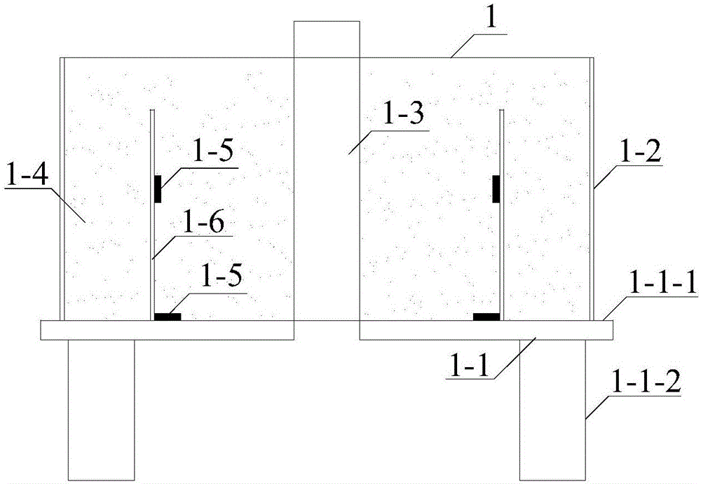
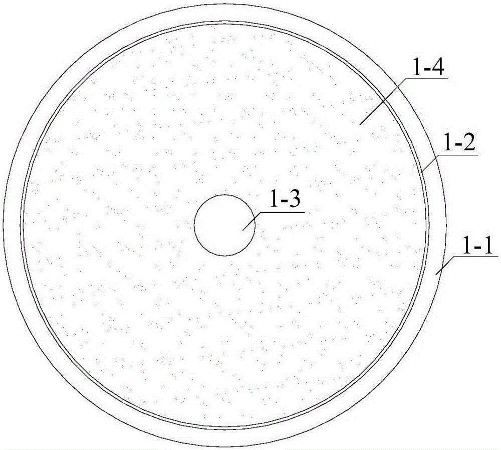
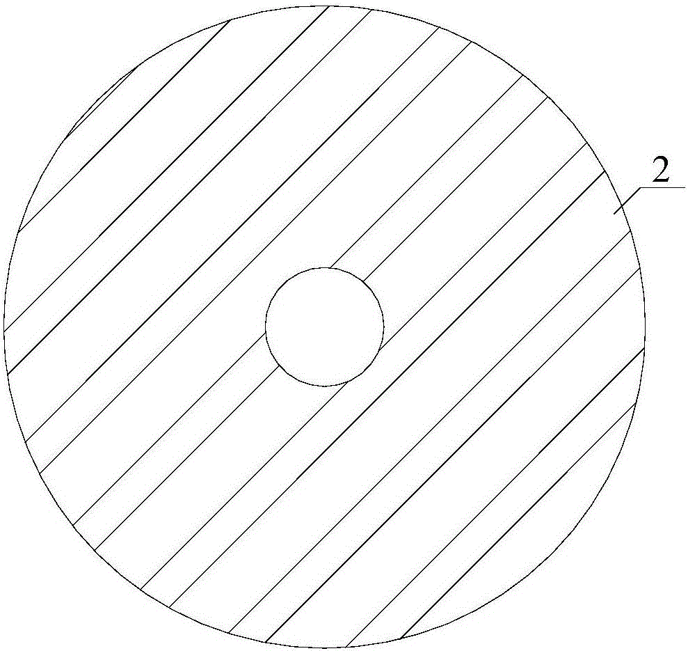
[0026] Such as figure 1 , Figure 4 As shown, the present invention is a pile-soil contact surface shear test device capable of simulating different sand density and different overlying pressures, including a circular model box 1, a loading plate 2, a reaction beam 3 and a servo loading device 4 in four parts.

[0027] Described circular model box 1 is made up of model box base 1-1 and circular model box frame 1-2; Described model box base 1-1 bottom plate 1-1-1 and support 1-1-2 are formed, bottom plate 1-1-1 is welded on the support 1-1-2; the base plate 1-1-1 is a 30mm thick steel plate with a diameter of 1000mm, and a round hole is provided at the center of the base plate; the support 1-1 -2 is welded by I-beam, with a height of 600mm; the circular model box frame 1-2 is made of 10mm thick steel plate, with a diameter of 900mm; the inside of the ...


PUM

PropertyMeasurementUnit
diameteraaaaaaaaaa

Abstract

The invention discloses a pile-soil interface shear test device capable of simulating change of an overburden pressure. The device comprises a round model box, a loading plate, a counter-force beam and a servo loading motor. The round model box is composed of a round frame and a base. Sandy soil at a certain density fills the model box, and a soil pressure sensor is placed in the sandy soil to test the vertical and horizontal soil pressures; the loading plate is placed on the upper surface of the sandy soil layer to apply the counter-force by means of a jack; the servo loading motor can be in two loading modes: displacement control and load control; a model pile at the center of the model box is loaded by means of the servo motor, and in the loading process, the load and displacement applied by the servo motor can be automatically collected. The device disclosed by the invention is reasonable in structure and simple to operate, and can be used for researching the frictional properties of the pile-soil interface under different overburden pressures, thereby providing an effective means for researching the frictional property of the pile-soil interface.

Description

technical field [0001] The invention relates to a pile-soil contact surface shear test device, in particular to a pile-soil contact surface shear test device with changes in overlying pressure, which can be used to study the relative density of sand and soil, the difference in the roughness of the pile surface and the overlying pressure Friction characteristics of pile-soil contact surface at different times. Background technique [0002] With the rapid development of urban construction in our country, many high-rise and super high-rise buildings have appeared, which require higher foundation bearing capacity. As a main form of foundation, pile foundation is widely used in foundation engineering. With the accumulation of actual engineering experience and the deepening of theoretical research in pile foundation engineering, many new types of piles have emerged on the basis of bored piles and prefabricated tubular piles. Foundations, such as extruded and expanded branch piles...

Claims


Application Information

Patent Timeline
Patent Type & Authority Applications(China)
IPC IPC(8): G01N3/08
CPCG01N3/08G01N2203/0019
Inventor 周佳锦龚晓南朱旻王奎华解才邵佳涵傅了一
Owner ZHEJIANG UNIV
Why Eureka
Try Eureka