Intra prediction pixel generation method and apparatus
A technology for predicting pixels and intra-frame prediction, which is applied in image communication, digital video signal modification, electrical components, etc. The effect of noise, the effect of improving coding efficiency
- Summary
- Abstract
- Description
- Claims
- Application Information
AI Technical Summary
Problems solved by technology
Method used
Image
Examples
Embodiment 1
[0062] Embodiment 1 uses a specific example to describe the method for generating intra-frame predicted pixels.
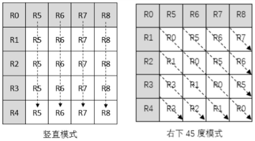
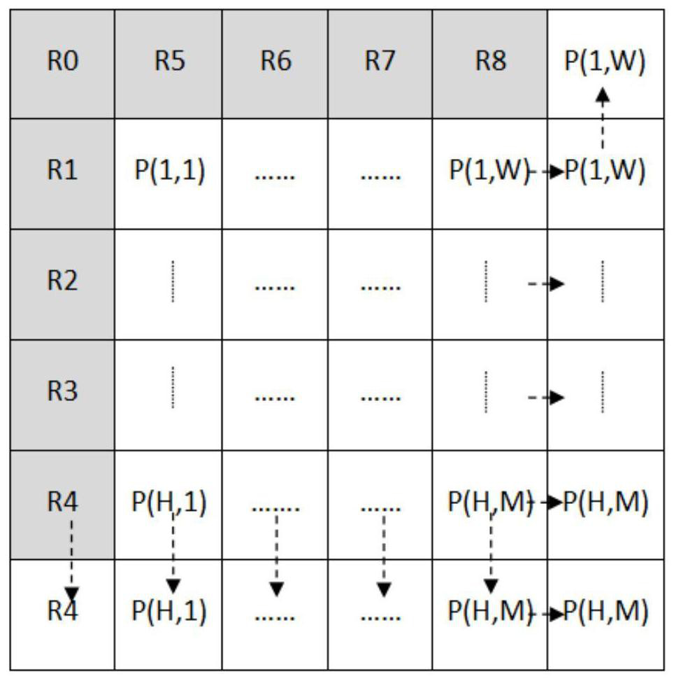
[0063] For a current block whose size is MxN and the intra-frame prediction mode is vertical mode (Vertical Mode), the first prediction pixel group PU whose size is MxN is generated according to the current intra-frame prediction mode 0 .
[0064] For the first prediction pixel group PU 0 Perform iterative filtering, including the following steps:
[0065] 1. For the first prediction pixel group PU 0 Carry out boundary expansion to obtain the expanded pixel group PU 1 , where PU 0 The pixel at the position above is filled by the reference pixel above it, PU 0 The pixel at the left position is filled by its left reference pixel, PU 0 The pixel at the lower position is copied to the PU 0 The pixel value of the bottom row, PU 0 The pixel value at the right position is copied to the PU 0 The pixel values of the rightmost column, such as figure 2 shown;
...
Embodiment 2
[0074] Embodiment 2 uses a specific example to describe the method for generating intra-frame predicted pixels.
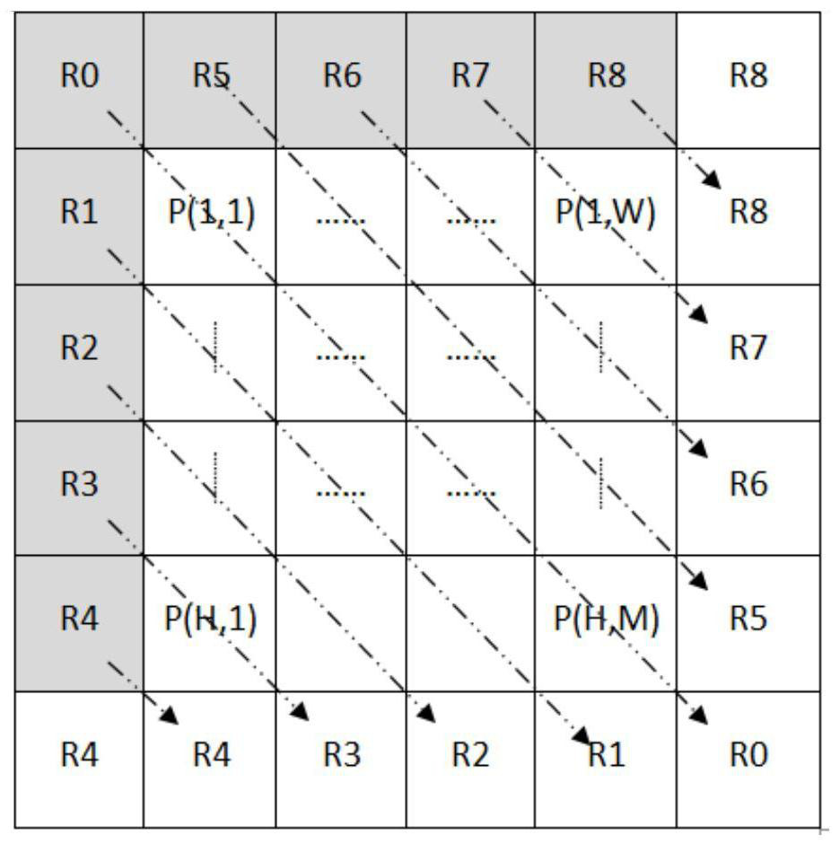
[0075] For a current block with a size of WxH and an intra-frame prediction mode of 45 degrees obliquely down to the right, generate the first prediction pixel group PU with a size of WxH according to the current intra-frame prediction mode 0 .
[0076] For the first prediction pixel group PU 0 Perform iterative filtering, including the following steps:
[0077] 1. For the first prediction pixel group PU 0 Carry out boundary expansion to obtain the expanded pixel group PU 1 , where the first prediction pixel group PU 0 The pixel at the upper position is filled with the reference pixel above it, and the first prediction pixel group PU 0 The pixel at the left position is filled with its left reference pixel, and the first prediction pixel group PU 0 The pixel at the lower position and the first prediction pixel group PU 0 The pixel value at the right position ...
Embodiment 3
[0084] Embodiment 3 uses a specific example to describe the method for generating intra-frame prediction pixels.
[0085] For a current block whose size is MxN and whose intra-frame prediction mode is a vertical mode, a first prediction pixel group PU whose size is MxN is generated according to the traditional intra-frame prediction mode 0 .
[0086] For prediction block PU 0 Perform iterative filtering, including the following steps:
[0087] 1. For the first prediction pixel group PU 0 Carry out boundary expansion to obtain the expanded pixel group PU 1 , where PU 0 The pixel at the position above is filled by the reference pixel above it, PU 0 The pixel at the left position is filled by its left reference pixel, PU 0 The pixel at the lower position is copied to the PU 0 The pixel value of the bottom row, PU 0 The pixel value at the right position is copied to the PU 0 the pixel values of the rightmost column;
[0088] 2. For the expanded pixel group PU 1 The it...
PUM
 Abstract
Description
Claims
Application Information
 - R&D
- Intellectual Property
- Life Sciences
- Materials
- Tech Scout
- Unparalleled Data Quality
- Higher Quality Content
- 60% Fewer Hallucinations
Browse by: Latest US Patents, China's latest patents, Technical Efficacy Thesaurus, Application Domain, Technology Topic, Popular Technical Reports.
© 2025 PatSnap. All rights reserved.Legal|Privacy policy|Modern Slavery Act Transparency Statement|Sitemap|About US| Contact US: help@patsnap.com


