
Method of operating an adjustable roll stabilizer

A stabilizer, adjustable technology used in interconnection systems, elastic suspensions, control systems, etc.

Pending Publication Date: 2021-03-05
ZF FIEDRICHSHAFEN AG
View PDF2 Cites 0 Cited by
  • Summary
  • Abstract
  • Description
  • Claims
  • Application Information

AI Technical Summary

Problems solved by technology

[0004] In addition to the structural design of the adjustable roll stabilizer, its proper handling is also a technical challenge

Method used


Image

  • Method of operating an adjustable roll stabilizer
  • Method of operating an adjustable roll stabilizer
  • Method of operating an adjustable roll stabilizer

Examples


Embodiment Construction

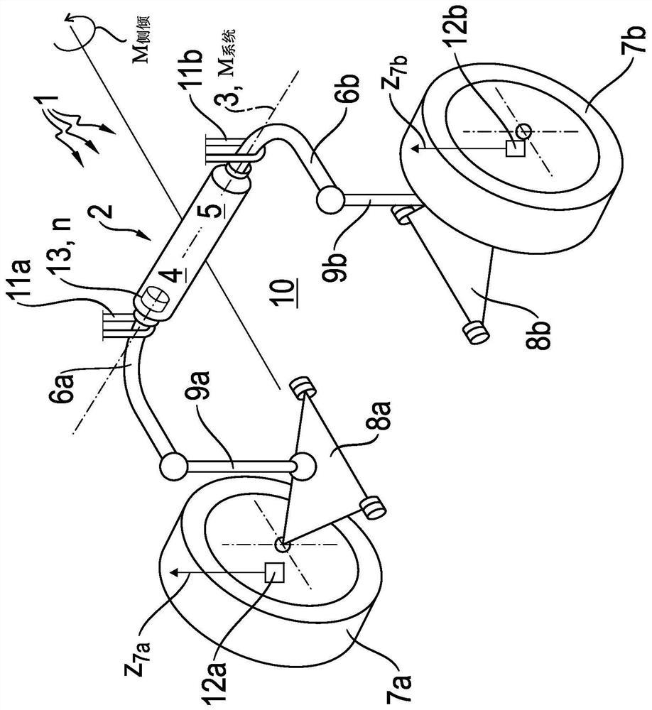
[0024] To demonstrate the field of application of the invention, figure 1First, the adjustable roll stabilizer 1 is shown in a schematic illustration. The adjustable roll stabilizer 1 is part of a not completely shown chassis of a (not shown) motor vehicle. The reference numerals designate only the vehicle structure 10 of the motor vehicle. The roll stabilizer 1 is also part of an axle of a motor vehicle, for example the front and / or rear axle of a motor vehicle may be equipped with an adjustable roll stabilizer 1 .

[0025] Such as figure 1 As shown, the left wheel 7 a and the right wheel 7 b arranged on the opposite vehicle side are each connected to the vehicle structure 10 via a steering mechanism 8 a or 8 b , not explained in detail. Thus, the wheel 7a and the steering mechanism 8a or the wheel 7b and the steering mechanism 8b each constitute a unit and are each coupled to the associated stabilizer section 6a or 6b of the adjustable roll stabilizer 1 by means of a pivo...


PUM


Abstract

A method of operating an adjustable roll stabilizer (1) of a motor vehicle. The adjustable roll stabilizer (1) includes an actuator (2) which can rotate relative to a rotational axis (3) in order to twist two stabilizer sections (6a, 6b) connected thereto relative to one another about the rotational axis (3). The stabilizer sections (6a, 6b) are radially spaced away from the rotational axis (3) and each is coupled to a wheel suspension (7a, 7b, 8a, 8b, 9a, 9b). The actuator (2) is controlled on the basis of a system target torque specified for the vehicle, and the specified system target torque is tested for acceptability in relation to a roll torque distribution (beta) that is acceptable for the motor vehicle.

Description

technical field [0001] The invention relates to a method for operating an adjustable roll stabilizer of a motor vehicle, and to a double-axle motor vehicle. Background technique [0002] It is known from motor vehicle technology, in particular chassis technology, to influence the rollover or rolling behavior of a motor vehicle by means of so-called roll stabilizers. In the basic structure, the roll stabilizer is here a substantially C-shaped torsion bar spring, which is rotatably mounted in the central region relative to the vehicle structure and whose opposite outer ends are connected by means of coupling elements (so-called swing struts) and are correspondingly coupled to the wheel suspension. With this construction, the roll stabilizer ensures that the body of the vehicle not only presses down on the outside side of the bend (due to centrifugal force) when cornering, but also ensures that the wheels on the inside of the bend are slightly lowered. Roll stabilizers increa...

Claims


Application Information

Patent Timeline
Patent Type & Authority Applications(China)
IPC IPC(8): B60G21/10
CPCB60G21/10B60G2200/341B60G2204/82B60G17/0157B60G21/0555B60G2400/252B60G2600/08B60G2600/09H02P21/22B60G2400/204H02P21/10
Inventor S·莱康H·埃勒G·霍尔兹M·贝尔T·霍德里厄斯J·恩格尔
Owner ZF FIEDRICHSHAFEN AG
Learn More