Video signal transmitting device, video signal receiving device, and video signal transmission and reception system

A video signal transmission, video signal technology, applied in the direction of closed-circuit television system, video conferencing system, TV system components, etc., can solve the problem of cost increase

Pending Publication Date: 2021-03-05
THINE ELECTRONICS
View PDF1 Cites 0 Cited by
  • Summary
  • Abstract
  • Description
  • Claims
  • Application Information

AI Technical Summary

Problems solved by technology

However, when two transmission lines are provided in this way, compared with the case of providing one transmission line, not only the cost increases due to the increase of necessary parts, but also the connectio

Method used


Image

  • Video signal transmitting device, video signal receiving device, and video signal transmission and reception system
  • Video signal transmitting device, video signal receiving device, and video signal transmission and reception system
  • Video signal transmitting device, video signal receiving device, and video signal transmission and reception system

Examples


Embodiment Construction

[0034] Hereinafter, modes for implementing the present invention will be described in detail with reference to the drawings. In addition, in the description of the drawings, the same reference numerals are attached to the same elements, and overlapping descriptions are omitted. The present invention is not intended to be limited to these examples, but is indicated by the claims, and all changes within the meaning and range equivalent to the claims are included.

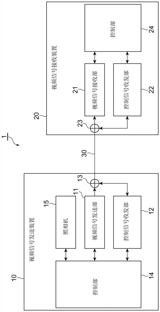
[0035] figure 1 It is a diagram showing the configuration of the video signal transmitting and receiving system 1 . The video signal transceiving system 1 includes a video signal transmitting device 10 and a video signal receiving device 20 connected to each other through a transmission line 30 . The video signal transceiving system 1 transmits video signals and control signals between the video signal transmitting device 10 and the video signal receiving device 20 via a common transmission line 30 .

[0036] The v...


PUM


Abstract

The invention provides a video signal transmitting device, a video signal receiving device, and a video signal transmission and reception system. The video signal transmission and reception system (1)performs transmission of a video signal and a control signal between the video signal transmitting device (10) and the video signal receiving device (20) via a common transmission line (30). The video signal transmitting device (10) includes a video signal transmitter (11), a control signal transmitter and receiver (12), a filter circuit (13), a controller (14), and a camera (15). The video signal receiving device (20) includes a video signal receiver (21), a control signal transmitter and receiver (22), a filter circuit (23), and a controller (24). By performing time management control performed by the controller (14) or the controller (24) such that the period of the transient state of transmission of the video signal is within the non-communication period of the control signal, interference between the video signal and the control signal in the period of the transient state of transmission of the video signal is suppressed.

Description

technical field [0001] The invention relates to a video signal sending device, a video signal receiving device and a video signal transceiving system. Background technique [0002] In recent years, cameras have been installed in various places. For example, cameras are installed at various places on the production line of a factory to monitor the production status, and when any failure occurs in the production line, prompt processing can be taken. In a medical field, for example, a camera is installed at the tip of an endoscope to monitor the inside of a patient, and appropriate treatment can be given to the patient based on the monitoring results. In addition, by installing a plurality of on-board cameras in passenger cars to monitor surrounding traffic conditions, etc., it contributes to the improvement of safe driving. [0003] As can be seen from these examples, the camera needs to be installed at a position where the target object can be photographed. On the other han...

Claims


Application Information

Patent Timeline
IPC IPC(8): H04N5/04H04N5/21H04N5/232H04N5/38H04N5/44
CPCH04N5/04H04N5/21H04N5/38H04N5/44H04N23/67H04N23/667H04N7/183H04N7/10H04N21/43632H04L5/0091H04N7/15H04N7/147H04N7/18H03H7/09H04N7/08
Inventor 藤木礼岩间大介井手口峻
Owner THINE ELECTRONICS
Why Eureka
Try Eureka