Electronic apparatus, electronic camera, electronic device, image display apparatus, and image transmission system

a technology of electronic camera and image display, applied in the field of electronic camera, electronic device, image display apparatus, image transmission system, can solve the problems of user's onus, electronic apparatus cannot be used immediately, risk of missing a good photo opportunity, etc., to achieve the effect of effectively preventing an erroneous identification and speeding up user identification

Active Publication Date: 2005-01-06
NIKON CORP
View PDF22 Cites 459 Cited by
  • Summary
  • Abstract
  • Description
  • Claims
  • Application Information

AI Technical Summary

Benefits of technology

[0018] The present invention provides, preferably, an electronic apparatus that has a user identification function for performing identification of the user of the electronic apparatus through a wireless method so as to speed up the user identification without placing an onus on the user and for effectively preventing an erroneous identification that would identify a party other than the user when executing the user identification through the wireless method and a user identification method that may be adopted in the electronic apparatus.

Problems solved by technology

However, having to directly load a magnetic card or a memory card at the electronic apparatus or connect the magnetic card or the memory card to the electronic apparatus, by means of wiring, each time the user needs to use the electronic apparatus places a considerable onus on the user and, moreover, there is a problem in that the electronic apparatus cannot be used immediately in a situation that arises suddenly.
For instance, there is a risk of missing a good photo opportunity while setting the personal information in the digital camera.
In addition, in the electronic apparatus in the related art described above, the personal information is utilized for limited purposes such as the automatic selection of the recipient to which images are to be transmitted and setting and display operations are performed in the electronic apparatus without fully reflecting the personal information.
As a result, the user may not always be satisfied with the ease of operation it affords.
The design of the electronic apparatus is particularly lax in consideration of users such as first-time users, seniors and children, who may not be accustomed to operating electronic apparatuses.
The user reviewing electronic image data in the related art as described above is simply allowed to view the reproduced images on display, and there is difficulty in expanding the range of information utilization beyond reviewing of the images.
In addition, if the user becomes interested in a person (the person's name, hobby, etc.) photographed in the image he is reviewing, the user cannot obtain that person's personal information immediately on the spot.
There are disadvantages to the off-line image transmission system and the off-line image transmission method in the related art described above in that since they necessitate an exchange of an information storage medium such as a memory card between the electronic camera and the image display terminal, the storage medium must be frequently loaded and unloaded, and data cannot be obtained and recorded through a photographing operation in the meantime, and in that since the recording medium must be physically transported, there is a time lag before the data can be utilized on the recipient side.
While the need to transport the information recording medium is eliminated by adopting the on-line transmission system and the on-line image transmission method in the related art described above, there is a problem in that data cannot be obtained and recorded through a photographing operation or the like while communication is in progress at a low transmission speed.
In particular, the length of time required to transmit image data the volume of which is much larger than that of standard text data or the like tends to be very significant.
Furthermore, when image data of a group picture of a number of people taken with an electronic camera are directly transmitted by the electronic camera to portable telephones or the like of the plurality of subjects, the image data transmission takes a great deal of time.

Method used


Image

  • Electronic apparatus, electronic camera, electronic device, image display apparatus, and image transmission system
  • Electronic apparatus, electronic camera, electronic device, image display apparatus, and image transmission system
  • Electronic apparatus, electronic camera, electronic device, image display apparatus, and image transmission system

Examples


first embodiment

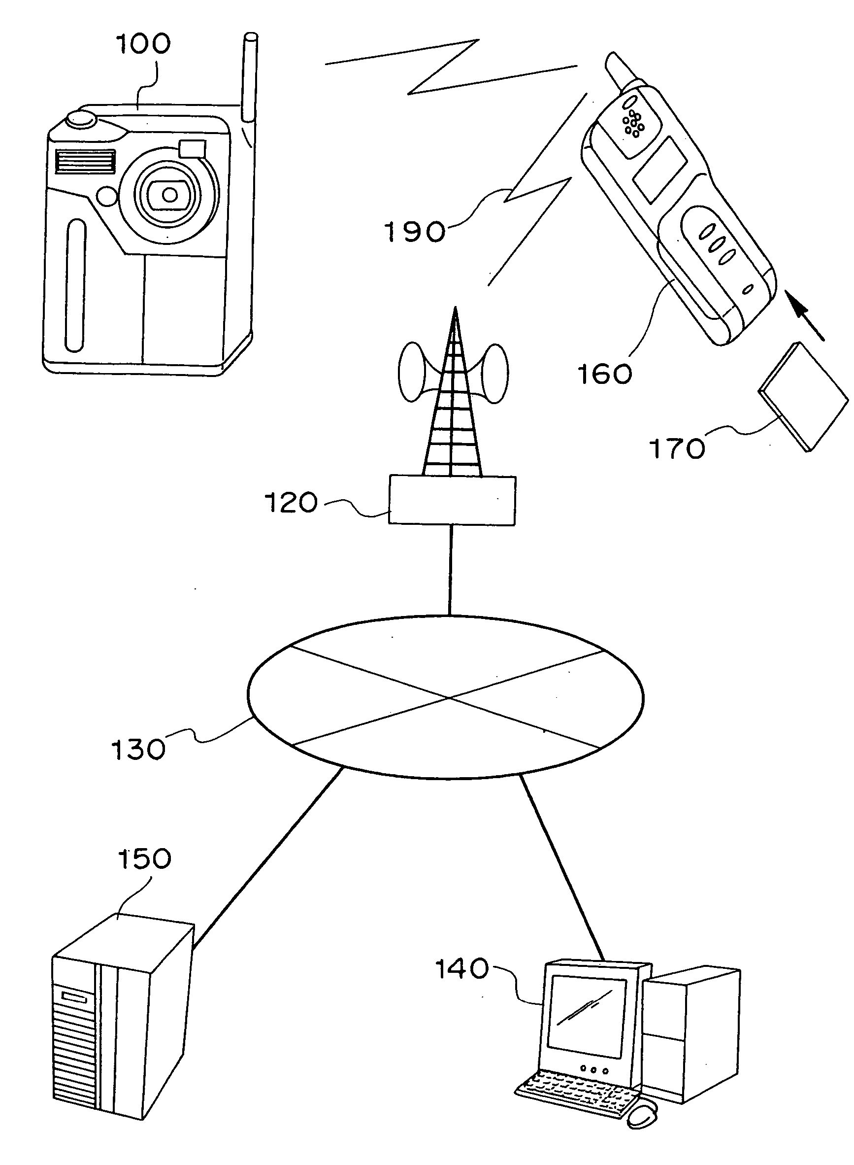
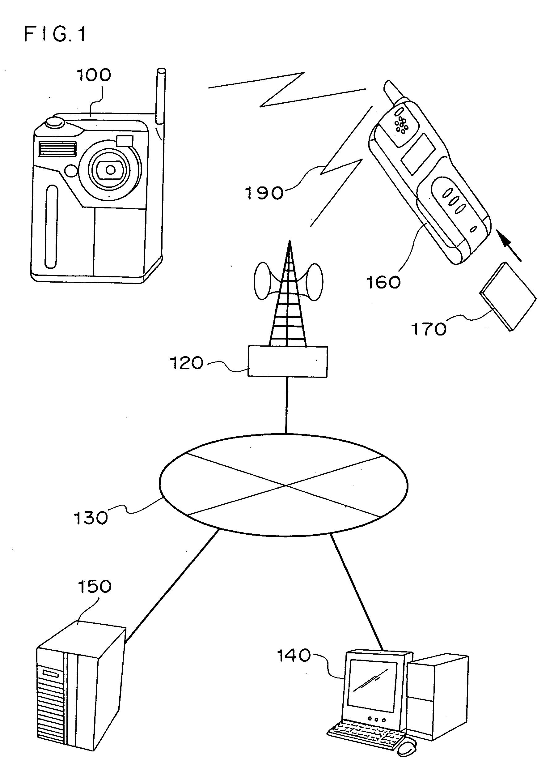
[0157] The first embodiment of the present invention is explained in reference to the drawings. FIG. 1 is a conceptual diagram of an electronic camera adopting the present invention and an electronic image communication system achieved by utilizing the electronic camera. In FIG. 1, an electronic camera 100 that includes a memory card saves electronic image data or digital image data (hereafter referred to as image data) obtained through a photographing operation into the memory card. In addition, the electronic camera 100 has a short-distance wireless communication function (e.g., Bluetooth (registered trademark; RTM) enabling communication within a range of approximately a 10M ) and engages in communication with a portable telephone 160 that also has a short-distance wireless communication function. It is assumed that this portable telephone 160 is carried by a user of the electronic camera 100 and that a UIM card (user identification module card) 170 having stored therein user per...

second embodiment

[0276] The second embodiment of the present invention is now explained in reference to the drawing. In the conceptual diagram of the second embodiment of the present invention presented in FIG. 56, an electronic camera that photographs a subject present within the photographing range also obtains related information from the subject and an information source present in the vicinity of the camera through wireless communication. In addition, the information related to the subject, which is made to correspond to the position of the subject within the photographic image plane, is appended to the image data obtained through the photographing operation together with other related information to constitute an image file.

[0277] When reproducing an image file, the image data having been obtained through a photographing operation are first reproduced and displayed as a home screen. Then, as the position within the image plane is specified at the home screen, the information related to the su...

third embodiment

[0377] The third embodiment of the present invention is now explained in reference to the drawings. FIG. 98 is a conceptual diagram of the third embodiment of the present invention. An electronic camera photographs subjects within the photographing range, assigns a file name to image data obtained through the photographing operation, connects with an image server on the Internet and uploads the image data into a specific folder at the image server. In addition, the electronic camera transmits address information (the Internet address of the image server is equivalent to URL (Uniform Resource Locator), the folder name and the image data file name at the image server) to electronic instruments (such as portable telephones) carried by the subjects in the vicinity of the camera through short-distance wireless communication. The electronic instrument (such as a portable telephone) carried by a subject connects to the image server on the Internet based upon the information received from t...


PUM


Abstract

In an electronic apparatus having a user identification function or in a user identification method, an electronic apparatus and an electronic instrument having stored therein user personal information communicate in wireless with each other so as to enable the electronic apparatus to automatically identify the electronic apparatus user. If the electronic apparatus identifies a plurality of possible users, the electronic apparatus automatically selects the user by executing specific user identification processing.

Description

INCORPORATION BY REFERENCE [0001] The disclosures of the following applications are herein incorporated by reference: [0002] Japanese Patent Application No. 2001-368014 filed Dec. 3, 2001 [0003] Japanese Patent Application No. 2001-373831 filed Dec. 7, 2001 [0004] Japanese Patent Application No. 2001-375568 filed Dec. 10, 2001 TECHNICAL FIELD [0005] The present invention relates to an electronic apparatus that identifies a user and performs an operation corresponding to the user and a method for identifying a user of an electronic apparatus and identifying an electronic apparatus to be utilized by the user and, more specifically, it relates to an electronic apparatus that identifies a user through communication executed between the electronic apparatus and the user and a method for identifying an electronic apparatus user and an electronic apparatus to be utilized by a user by executing communication between the electronic apparatus and the user. [0006] The present invention also re...

Claims


Application Information

Patent Timeline
Patent Type & Authority Applications(United States)
IPC IPC(8): H04N1/00
CPCH04N1/00281H04N1/0097H04N5/23293H04N1/00106H04N5/225G06F3/005H04N1/00251H04N1/00153H04N1/2125H04N1/00114H04N1/00129H04N1/32101H04N23/661H04N23/631G08B13/19656G06V40/16G06F2218/12H04N23/00H04N23/56H04N23/57H04N23/62H04N23/64H04N23/611H04N23/667G06F3/041G06F3/04883G06F2203/04808H04N2201/0084H04N5/44
Inventor KUSAKA, YOSUKENAKAMURA, SHOEI
Owner NIKON CORP
Why Eureka
Try Eureka