Ice breaking device applied to bulbous bow of polar ship

A ball nose bow and ship technology, which is applied in the direction of icebreakers, etc., can solve the problems of bow structure damage, difficult control of ice hammer, low efficiency, etc., and achieve the effect of reducing wave resistance and coherent and efficient icebreaking

Active Publication Date: 2021-03-12
JIANGSU UNIV OF SCI & TECH
View PDF20 Cites 2 Cited by
  • Summary
  • Abstract
  • Description
  • Claims
  • Application Information

AI Technical Summary

Problems solved by technology

This method is inefficient and difficult to control, and seriously damages the bow structure. The ice on the bow is likely to freeze again after breaking the ice, enclosing the ship in ice
[0004] The Chinese patent with application number 201420755640.9 discloses a snow and ice removal device, which includes a box body and walking wheels arranged at the bottom of the box body. The box body is equipped with an ice breaking device, an ice crushing device, an ice suction device and a driver, but it has the following disadvantages : 1. The ice-breaking blades are on both sides of the box, and the cut ice is as wide as the box. The ice-breaking device is also at the same width as the box. The effect of the ice-breaking knife is not obvious; When it is stationary, it can only control its vertical height. If you want to accurately align the ice-breaking position, you need to adjust the position of the box back and forth, so the ice-breaking hammer is not easy to control. Thick values ​​can only be judged based on human experience, not smart enough, resulting in low efficiency
However, relying on the bulbous bow to break the ice, the method is single, the efficiency is low, the structural strength of the bow is strong, and the bulbous bow is easy to damage

Method used


Image

  • Ice breaking device applied to bulbous bow of polar ship

Examples


Embodiment Construction

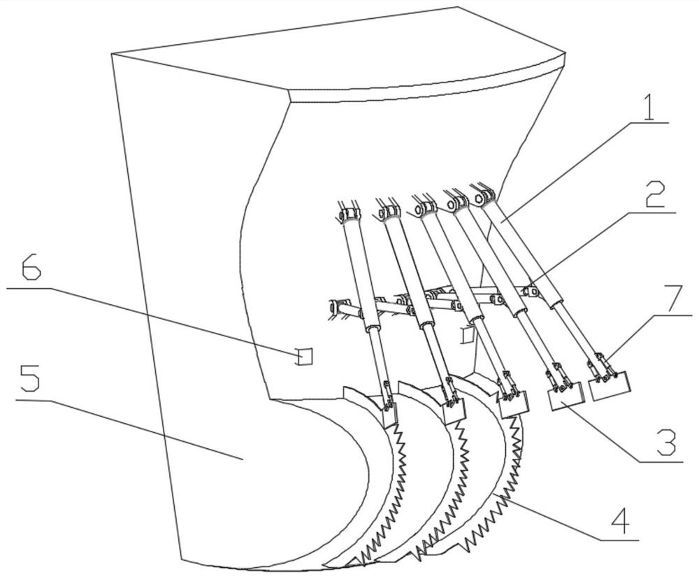
[0018] like figure 1 , The ice-breaking device includes several groups of main support arms 1, secondary support arms 2 and ice-breaking blades 3, one end of the main support arm 1 is hinged on the bow outer plate, and the other end is hinged to the ice-breaking blade 3. The midpoints of the upper and lower sections of the ice-breaking knife 3 are respectively hinged with the main support arm 1 by two support rods 7, and the support rod 7 can adjust the inclination angle of the ice-breaking knife 3 through length expansion and contraction, so as to flexibly select the optimal ice-breaking angle. One end of the secondary support arm 2 is hinged on the lower side of the bow outer plate and the connection point of the main support arm 1, and the other end is hinged on the main support arm 1. The main support arm 1 and the secondary support arm 2 can be telescopically adjusted in length, and rotated to adjust their direction. When breaking the ice, the falling device controls the...


PUM


Abstract

The invention discloses an ice breaking device applied to a bulbous bow of a polar ship. The ice breaking device comprises a main supporting arm, a secondary supporting arm, an ice breaking knife andan ice breaking blade. One end of the main supporting arm is connected with a stem, and the other end is connected with the ice breaking knife; one end of the secondary supporting arm is connected with the stem, and the other end is connected with the main supporting arm; the ice breaking blade is arranged on the bulbous bow, and the main supporting arm, the auxiliary supporting arm and the ice breaking knife are all connected with a control device. By arranging the ice breaking knife and the ice breaking blade on the stem, an ice layer is gradually cut into small floating ice, icebreaking iscoherent and efficient, and repeated icebreaking is not needed; direct contact between the bulbous bow and an ice layer is reduced, the ice load borne by the bulbous bow is effectively reduced, the impact of the ice load on the bulbous bow is buffered, and the bow structure is safer; when the ship does not sail in the polar ice area, the device can be contracted and placed above the water line ofthe bow outer plate, the bulbous bow continues to reduce wave resistance, and the ship navigation speed is not affected.

Description

technical field [0001] The invention relates to an ice-breaking device, in particular to an ice-breaking device applied to a bulbous bow of a polar ship. Background technique [0002] With the advancement of science and technology and the continuous consumption of energy, human beings' desire for energy is becoming stronger and stronger. The opening of polar waterways has greatly enriched the available natural resources, and human activities in polar regions have become more and more frequent. However, the Arctic region has little sunlight exposure, a cold climate, and is covered with ice and snow all year round. The natural conditions are very harsh. The traditional icebreaker uses the pressurized water tank to adjust the draft at the fore and aft. When the bow is tilted, the horsepower is used to rush to the ice surface. At this time, the bow pressurized water tank is filled with water, and the weight of the bow increases to crush the ice surface, and then the icebreaker ...

Claims


Application Information

Patent Timeline
IPC IPC(8): B63B35/12
CPCB63B35/12
Inventor 罗广恩王陈阳李爽王一镜郑远昊刘俊成刘家奇
Owner JIANGSU UNIV OF SCI & TECH
Why Eureka
Try Eureka