
Sliding support monitoring device and method

A sliding bearing, monitoring device technology, applied in the direction of measuring devices, electrical devices, bridge parts, etc.

Pending Publication Date: 2021-03-12
HUNAN LIANZHI BRIDGE & TUNNEL TECH
View PDF0 Cites 0 Cited by
  • Summary
  • Abstract
  • Description
  • Claims
  • Application Information

AI Technical Summary

Problems solved by technology

[0004] The purpose of the present invention is to provide a sliding support monitoring device and method to solve the problem of real-time monitoring of the sliding state of the sliding support

Method used


Image

  • Sliding support monitoring device and method
  • Sliding support monitoring device and method
  • Sliding support monitoring device and method

Examples


Embodiment

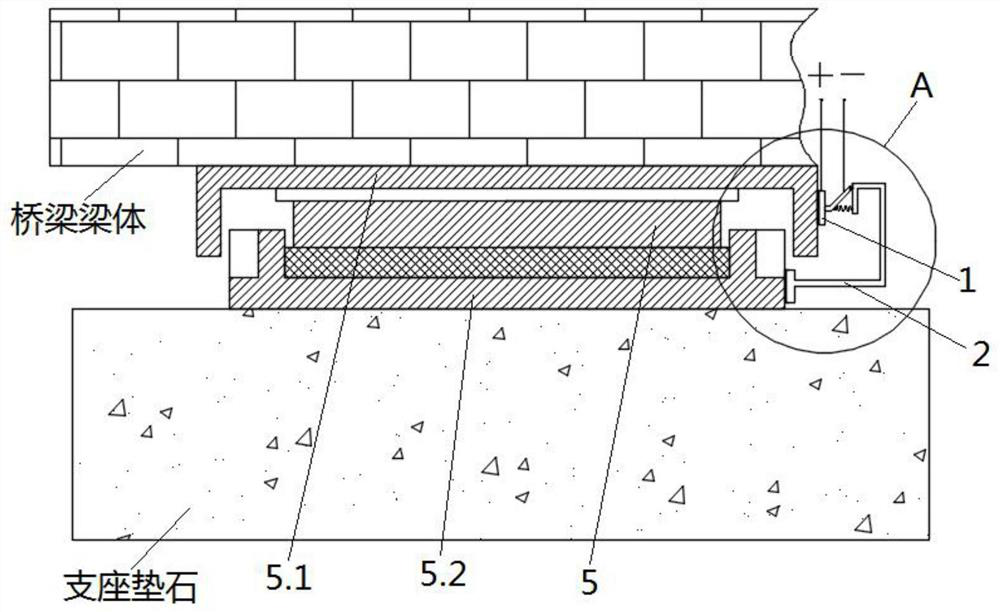
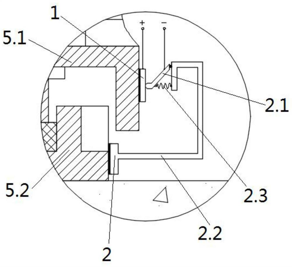
[0036] see Figure 1 to Figure 3 , a sliding bearing monitoring device and method, this embodiment is applied to the monitoring of the sliding state of the sliding bearing 5, the sliding bearing 5 is a one-way sliding bridge basin rubber bearing.

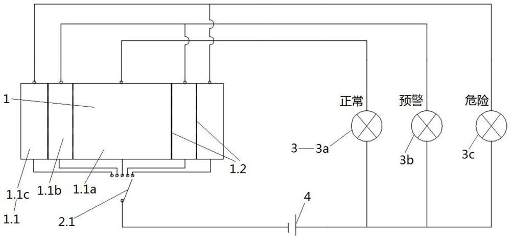
[0037] A sliding support monitoring device, comprising a conductive unit 1 and a conductive support 2, the conductive unit 1 and the conductive support 2 are respectively arranged on two relatively sliding support plates of the sliding support 5; the conductive unit 1 includes multiple A conductive block 1.1 arranged along the sliding direction of the sliding support 5, adjacent conductive blocks 1.1 are separated by an insulating member 1.2; the conductive support 2 includes a conductive contact rod 2.1, and the conductive contact rod 2.1 is connected to one of the conductive blocks. 1.1 Contact conduction; each conductive block 1.1 is connected to the conductive contact rod 2.1 through a connecting line, and each connecting line i...


PUM


Abstract

The invention provides a sliding support monitoring device. The monitoring device comprises a conductive unit and a conductive support, and the conductive unit and the conductive support are arrangedon two support plates which slide relatively of the sliding support respectively. The conductive unit comprises a plurality of conductive blocks arranged in the sliding direction of the sliding support, and the adjacent conductive blocks are spaced through insulating parts; the conductive support comprises a conductive feeler lever, and the conductive feeler lever is in contact conduction with oneof the conductive blocks; each conductive block is connected with the conductive feeler lever through a connecting line, and each connecting line is provided with a state display part used for displaying the sliding state of the sliding support. The invention further provides a sliding support monitoring method. The method comprises installing a sliding support, arranging conductive blocks, installing a sliding monitoring device and carrying out real-time monitoring. The sliding state of the sliding support can be monitored in real time by contacting the conductive contact rod with differentconductive blocks and communicating different state display pieces.

Description

technical field [0001] The invention relates to the technical field of building construction, in particular to a sliding support monitoring device and method. Background technique [0002] Bridge pot rubber bearings are commonly used sliding bearings. At present, there are two main measurement methods for the slippage of bridge basin rubber bearings: one is through manual periodic measurement, and the measurement method is to detect the relative position of the upper bearing plate and the lower bearing plate each time, and the upper bearing plate The change of the relative position with the lower bearing plate determines the sliding amount of the bearing; the detection cycle of regular measurement is generally 1 to 3 years, and the detection results lack timeliness. The other is to measure the slippage through the displacement sensor, but the displacement sensor needs to be used with the reading instrument and the computer. After the monitoring data is processed in the back...

Claims


Application Information

Patent Timeline
Patent Type & Authority Applications(China)
IPC IPC(8): G01B7/02E01D19/04
CPCE01D19/048G01B7/02
Inventor 徐善中李鹏梁晓东刘志辉李求源曾国良
Owner HUNAN LIANZHI BRIDGE & TUNNEL TECH
Learn More