
Apparatus and method for determining rotation angle

A technology of rotation angle and rotation axis, applied in the field of position or angle sensors, can solve the problems of positioning tolerance limit of angle accuracy sensor, wrong angle estimation, etc., to achieve the effect of low system cost, easy and cheap production and orientation

Active Publication Date: 2022-08-09
INFINEON TECH AG
View PDF20 Cites 0 Cited by
  • Summary
  • Abstract
  • Description
  • Claims
  • Application Information

AI Technical Summary

Problems solved by technology

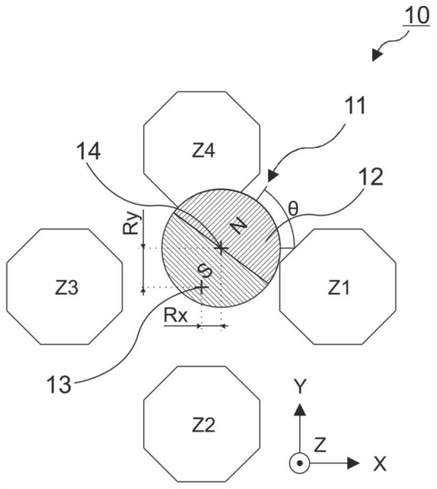
The angular accuracy of this arrangement is usually strictly limited by the positioning tolerances of the sensors
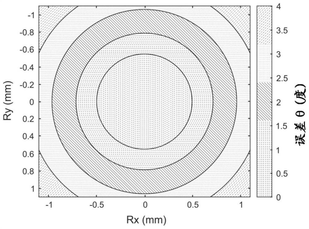
If one-tenth of the magnet diameter has been displaced or misaligned, this limits the achievable accuracy to approximately 1°
[0006] In practice, however, mechanical misalignment between the sensor element and the measurement object or magnet is usually not completely avoided, so there are different amplitudes, offsets and phase shifts of the periodic signals X and Y, which in turn lead to erroneous angle estimates

Method used


Image

  • Apparatus and method for determining rotation angle
  • Apparatus and method for determining rotation angle
  • Apparatus and method for determining rotation angle

Examples


Embodiment Construction

[0055] Various examples will now be described more fully with reference to the accompanying drawings, in which some examples are shown. In the drawings, the thickness of lines, layers and / or regions may be exaggerated for clarity.

[0056] Thus, while additional examples are capable of various modifications and alternative forms, some specific examples thereof are shown in the drawings and described in detail subsequently. However, this detailed description does not limit further examples to the particular forms described. Additional examples may cover all modifications, equivalents, and alternatives falling within the scope of this disclosure. Like reference numerals denote similar or similar elements in the description of the figures, which may be implemented in the same or in modified form when compared with each other, while providing the same or similar functionality.

[0057] It will be understood that when an element is referred to as being "connected" or "coupled" to...


PUM


Abstract

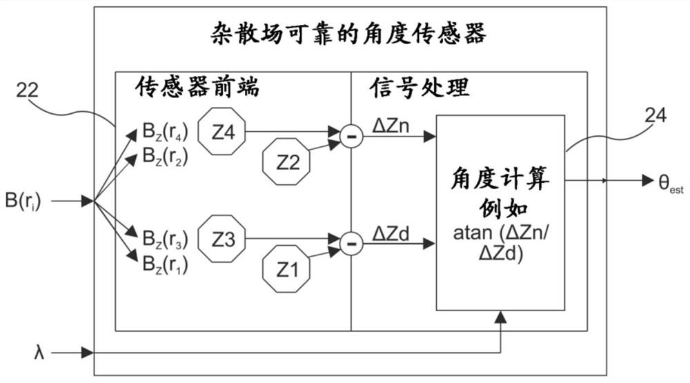
The present disclosure relates to a device for determining the angle of rotation of a measurement object influencing the orientation of a magnetic field, the measurement object having an axis of rotation in the z-direction, the device comprising: at least three first magnetic field sensor elements uniformly arranged around the axis of rotation, They are each sensitive to the magnetic field component in the z direction; at least three second magnetic field sensor elements uniformly arranged around the axis of rotation are each sensitive to the magnetic field component in the x‑y plane; 3. The device for determining the rotation angle of the fourth combined signal, the first combined signal is based on the first combination of the measurement signals of the first magnetic field sensor element, the second combined signal is based on the second combination of the measurement signals of the first magnetic field sensor element, and the third combined signal The fourth combined signal is based on the second combination of the measurement signals of the second magnetic field sensor element according to the first combination of the measurement signals of the second magnetic field sensor element.

Description

technical field [0001] The present disclosure relates generally to position or angle sensors, and more particularly to angle sensors that take into account mechanical misalignment between the sensor element and the measurement object. Background technique [0002] Magnetic position or angle sensors are used, for example, in the automotive environment to resolve linear and angular positions. The angle sensor can be realized, for example, by means of a magnetic field sensor, which is placed in the vicinity of a rotating measuring object, such as a shaft. In this case, the first measurement value (X) can be determined as a function of the magnetic field depending on the rotation angle θ of the measurement object. Furthermore, the second measurement value (Y) can be determined from the magnetic field depending on the rotation angle θ of the measurement object. Ideally, the two measurements correspond to periodic signals of the form X=A*cos(θ) and Y=A*sin(θ). The rotation angl...

Claims


Application Information

Patent Timeline
Patent Type & Authority Patents(China)
IPC IPC(8): G01B7/30G01B7/00G01D5/14
CPCG01B7/30G01B7/003G01D5/145G01D3/036
Inventor B·科尔米策T·盖纳
Owner INFINEON TECH AG
Learn More