
Differential angle sensor with multipole magnet

An angle sensor and multi-pole magnet technology, applied in the direction of converting sensor output, using electric/magnetic devices to transfer sensing components, instruments, etc., can solve the problems of flux loss and synthetic magnetic field not being optimized, and achieve reliable angle measurement, cost reduction effect

Pending Publication Date: 2020-06-23
SC2N SA
View PDF1 Cites 0 Cited by
  • Summary
  • Abstract
  • Description
  • Claims
  • Application Information

AI Technical Summary

Problems solved by technology

[0014] As a result, the resulting magnetic field generated by the magnet is not optimized and irreversible loss of flux can occur

Method used


Image

  • Differential angle sensor with multipole magnet
  • Differential angle sensor with multipole magnet
  • Differential angle sensor with multipole magnet

Examples


Embodiment Construction

[0038] The invention relates to an angle sensor for use in components of a vehicle motor, such as an electric throttle controller (ETC) or an gas recirculation valve (EGR), for example to detect and / or precisely control the angular position of a valve. The angle sensor consists of two probes sensitive to magnetic fields. This type of angle sensor is called a differential angle sensor.

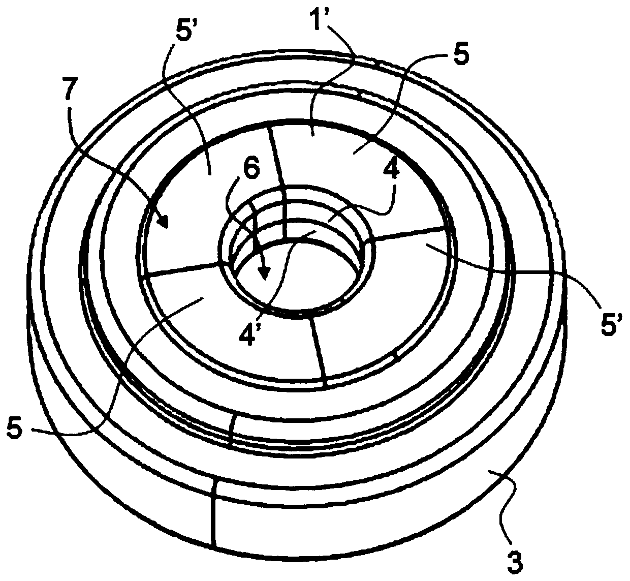
[0039] figure 1 is a schematic diagram of a prior art magnet 1'.

[0040] The angle sensor comprises an axial flux magnet 1 ′ fixed in an annular support 3 .

[0041] The assembly formed by the magnet 1' and the support 3 is intended to be fixed on a movable element of the vehicle motor, such as a shaft actuating a flap (not shown for simplicity).

[0042] Each probe sensitive to a magnetic field is able to detect changes in the magnetic field generated by the magnet 1' as it rotates, thereby making a differential measurement.

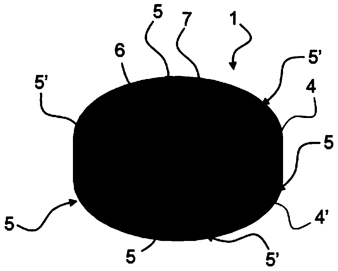
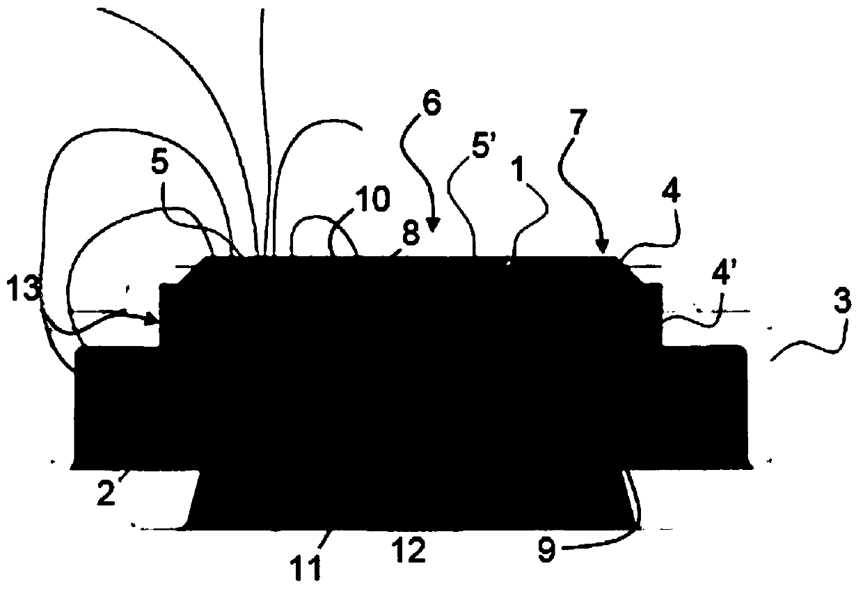
[0043] like figure 2 As shown, in the context of the present...


PUM


Abstract

The invention relates to an angle sensor for detecting the angular position of a rotating movable element in a motor of a motor vehicle. The angle sensor includes two probes that are sensitive to magnetic fields. Each probe can detect the change in the magnetic field generated by the axial flux multi-pole magnet (1) fixed on the movable element during rotation for differential measuring. Accordingto the present invention, the angle sensor includes a magnetic element (2) on which a multipole magnet (1) rests, and a magnetic element (2) is composed of a magnetic material in order to integrate the magnetic field on the front of the magnet and increase magnetic induction in the magnet (1).

Description

technical field [0001] The invention relates to an angle sensor for detecting the angular position of a rotationally movable element in a motor vehicle motor. Background technique [0002] Such angle sensors are used in components of vehicle motors, such as electric throttle controllers (ETC) or gas recirculation valves (EGR), for example to detect and / or precisely control the angular position of a valve. Other applications are also possible. [0003] Angle sensors usually include a magnet and a magnetic probe. The magnet has alternating north and south poles. Rotation of a magnet fixed to a movable element causes a change in the magnetic field. [0004] Magnetic probes are sensitive to the direction and magnitude of a magnetic field and deliver electrical signals based on the angle of that field. [0005] In vehicle motors, angle sensors are placed near electrical components or elements of the motor that generate strong magnetic fields, such as alternators, motors, or h...

Claims


Application Information

Patent Timeline
Patent Type & Authority Applications(China)
IPC IPC(8): G01D5/14G01B7/30
CPCG01D5/142G01B7/30G01D5/145G01D3/036G01D2205/40
Inventor V.吉贝特
Owner SC2N SA
Learn More