Eye accommodation distance measuring device and method, and head-mounted display

A technology for adjusting distance and eyes, used in augmented reality/virtual reality systems, head-mounted displays, and can solve problems such as lack of accuracy

Active Publication Date: 2021-03-12
SAMSUNG ELECTRONICS CO LTD
View PDF16 Cites 1 Cited by
  • Summary
  • Abstract
  • Description
  • Claims
  • Application Information

AI Technical Summary

Problems solved by technology

This known device estimates the depth of focus indirectly and does not provide the required accuracy

Method used


Image

  • Eye accommodation distance measuring device and method, and head-mounted display
  • Eye accommodation distance measuring device and method, and head-mounted display
  • Eye accommodation distance measuring device and method, and head-mounted display

Examples


no. 1 example

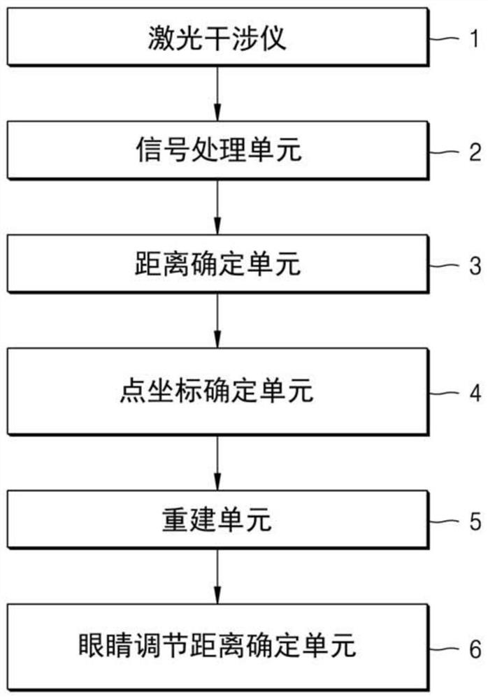
[0071] according to Figure 9 The first preferred embodiment of the present invention shown in the present invention is a self-mixing interferometer (SMI interferometer), and includes a laser array 11 (eg, a vertical cavity surface emission laser (VCSEL) Array), laser array driver 12 and optical systems.

[0072] The laser array driver 12 selectively supplies a modulated frequency modulated frequency modulated frequency modulated to the array while supplying all lasers of a laser, a set of lasers or laser array 11. The number of lasers running at the same time is limited by the maximum allowable laser radiation power for eye safety. Each of the lasers in the array has a specific beam direction different from each other, which is known in advance, and depends on the position of other parts of the device depending on the laser array 11 relative to the eye adjustment distance involved in the beam direction. .

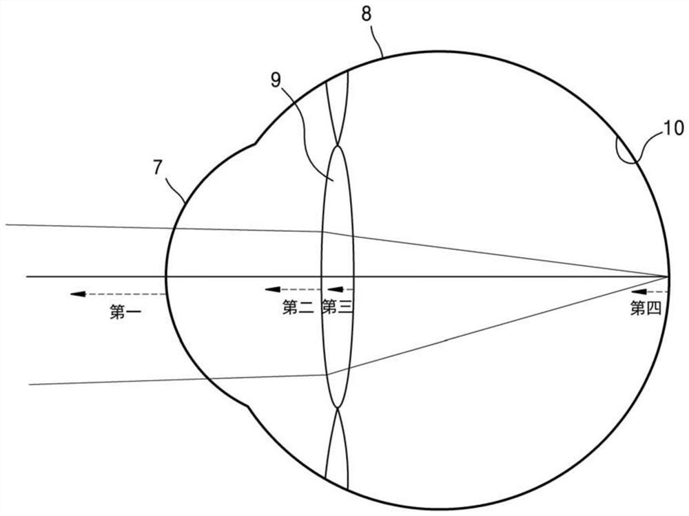
[0073] The optical system is involved in the direction of forming the bea...

no. 2 example

[0079] according to Figure 10 The second embodiment of the present invention shown in the present invention, the interferometer of the eye adjustment distance determining the apparatus is an armed array 11, a laser array driver 12, a laser array driver 12, a detector 15, a beam splitter 16, a reference mirror 17, and Optical system.

[0080] Laser arrays, laser array drivers, and optical systems correspond to the laser array, laser array driver, and optical system of the first embodiment, and will not be described again.

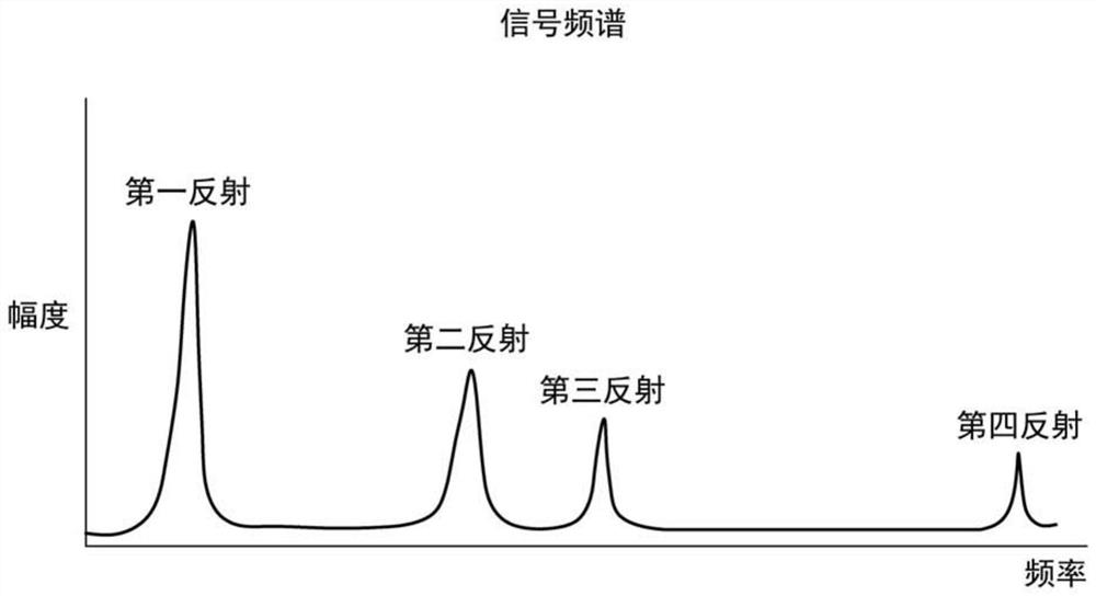
[0081] The second embodiment differs from the first embodiment in the method of generating an interference signal. The beams emitted by a particular laser of the array are divided into two beams, and one beam is reflected from the reference mirror 17, and the other beam is transmitted to the user's eyes and reflects from its surface. Both beams return to the beam splitter 16 and is sent to the detector 15 (see Figure 10 ), Two of which interferes with interfere...

no. 3 example

[0084] according to Figure 11 The third embodiment of the present invention shown in the present invention, the interferometer of the eye adjusting distance determines the device is a self-mixed interferometer, and includes a single laser 18, a laser driver, an optical mechanical scanning system, and an optical system.

[0085] The optical system of the present embodiment corresponds to an optical system of the previous embodiment, and is therefore not described again.

[0086] Similar to the first embodiment, the production of the interference signal is performed using a self-mixing effect, i.e., by measuring the laser bias voltage on the driver side or by using the photodiode in the laser package, the laser power oscillation is measured.

[0087] The optical mechanical scanning system provides a change in the direction of laser beam, and can be implemented using any prior art light deflection technique, for example, using a rotary mirror, a MEMS mirror, a movable lens, an acous...


PUM


Abstract

Provided are an eye accommodation distance determining device. The eye accommodation distance determining device includes: an interferometer configured to generate a plurality of frequency modulated laser beams in different directions and to generate a plurality of interferometric signals using laser beams reflected from eye reflecting surfaces, a signal processing unit configured to generate a signal spectrum using each of said plurality of interferometric signals, a distances determining unit configured to determine distances to the eye reflecting surfaces for each of said plurality of laserbeams, a points coordinates determining unit configured to determine coordinates of points on each of the eye reflecting surfaces for each of the laser beams, a reconstruction unit configured to generate an eye inner structure model based on the determined coordinates of points, and an eye accommodation distance determining unit configured to determine, based on said eye inner structure model, aneye accommodation distance.

Description

Technical field [0001] The present invention relates to the field of stereoscopic display, and more particularly to an eye adjustment distance measuring apparatus and method for a head-mounted display, and a corresponding head mounted display, and can be used to enhance the reality / virtual reality system (AR / VR). Background technique [0002] The 3D object perceived physiological principle in the real world requires eye focus (adjustment distance) and eye convergence points (converging distance). These values ​​do not match in a commercial AR / VR system having a fixed focal length, which results in a so-called visual spokes to regulate collisions (VAC), and thus make user fatigue and visual discomfort. When using the AR glasses, the VAC effect makes the process of matching the real object and the virtual object, because when the real object is observed, the virtual object may defocus. This problem can be measured (track) by automatic eye focus and feedback to the AR glasses ...

Claims


Application Information

Patent Timeline
Patent Type & Authority Applications(China)
IPC IPC(8): G02B27/01G06T19/00G01S17/08
CPCG02B27/017G06T19/006G01S17/08G02B27/0172G01S17/34G01S7/4916G01S7/4815G01S7/4812G01S7/493G01S7/4915G01S17/88A61B3/09G01B9/02004G01B9/02007G01B9/02092
Inventor 弗拉季斯拉夫·瓦列里维奇·雷查戈夫弗拉基米尔·米哈伊洛维奇·谢苗诺夫叶夫根尼亚·尤里耶夫娜·萨拉马托娃
Owner SAMSUNG ELECTRONICS CO LTD
Why Eureka
Try Eureka