Sterilization and disinfection device for gynecological applicator
A technology for sterilization and disinfection devices and applicators, which is applied in the direction of disinfection, water supply devices, and sanitary equipment for toilets, etc. It can solve the problems of incomplete sterilization, increased treatment costs, overlapping applicators, etc., and achieve improved sterilization and disinfection effects , Improve the effect of disinfection
- Summary
- Abstract
- Description
- Claims
- Application Information
AI Technical Summary
Problems solved by technology
Method used
Image
Examples
Embodiment 1
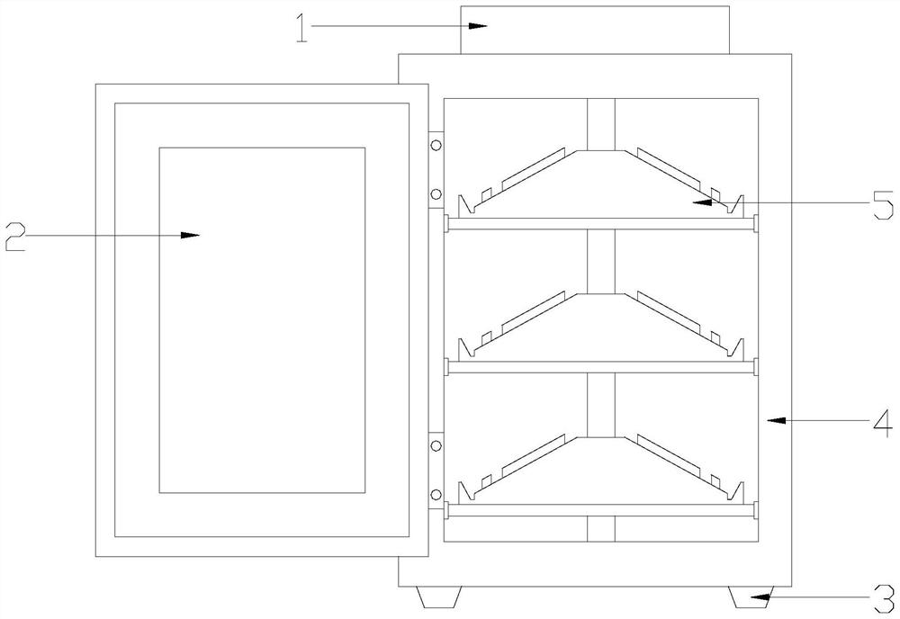
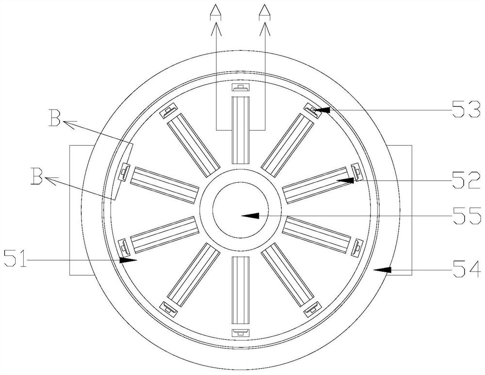
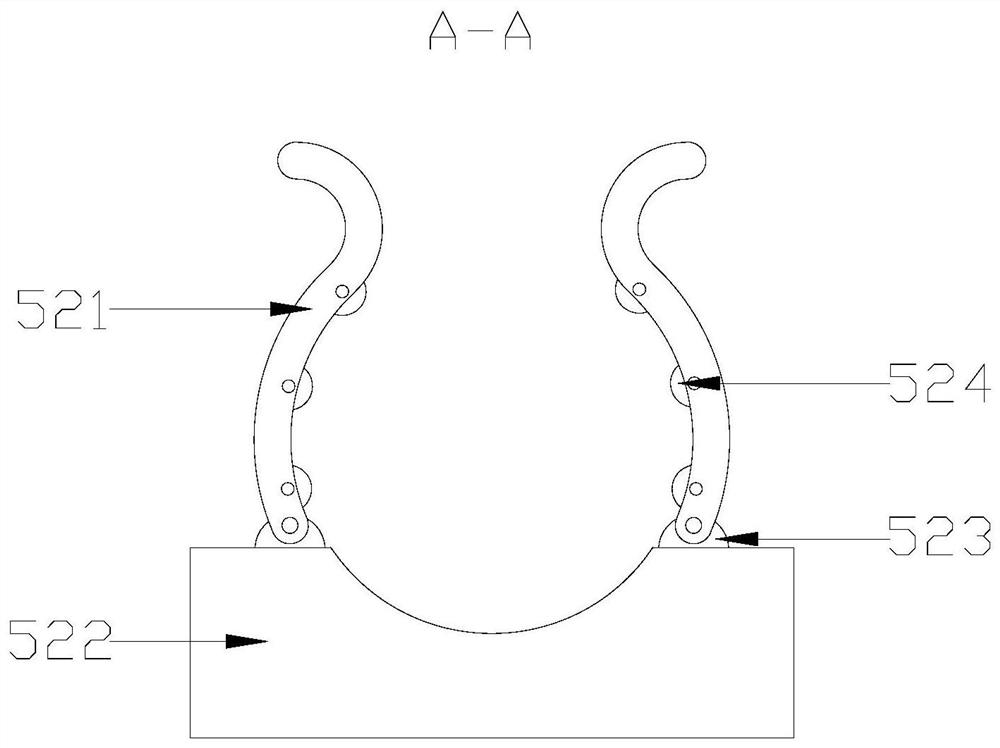
[0027] see Figure 1-Figure 6 , the present invention provides a gynecological applicator sterilization and disinfection device, its structure includes a control panel 1, a protective door 2, a support foot 3, a disinfection cabinet body 4, and a rotating disinfection device 5, and the disinfection cabinet body 4 is rectangular structure and placed vertically, the protective door 2 is connected to the front of the protective door 2 through a hinge, the control panel 1 is nested on the top of the main body 4 of the disinfection cabinet, and the supporting feet 3 are fixed on the bottom surface of the main body 4 of the disinfection cabinet by threads At the four corners, the rotating disinfection device 5 is equidistantly evenly distributed inside the main body 4 of the disinfection cabinet; Drive shaft 55 is formed, and described rotary drive device 54 is provided with three and is horizontally nested in disinfection cabinet main body 4 interior respectively, and described dri...
Embodiment 2
[0030] see Figure 7-Figure 8 , the fixed base 522 is composed of a liquid inlet a1, a liquid discharge pipe a2, a base main body a3, an accommodating tank a4, and a scraper plate a5, and the base main body a3 is uniformly distributed on the upper surface of the rotating frame 51 in an annular array , the scraper a5 is horizontally nested inside the base body a3, the liquid inlet a1 runs through and connects to the upper and lower ends of the scraper a5 equidistantly from left to right, and the accommodating groove a4 is located in the base body a3 And located above the scraper a5, the drain pipe a2 is nested in the base body a3 and located below the scraper a5. The rotating frame 51 is provided with a branch pipe b1 and a confluence pipe b2. The branch pipe b1 and the end of the discharge pipe a2 away from the drive shaft 55 communicate with each other and are installed under the rotating frame 51. The confluence pipe b2 is located at the bottom of the rotating frame 51 and ...
PUM
 Abstract
Description
Claims
Application Information
 - R&D
- Intellectual Property
- Life Sciences
- Materials
- Tech Scout
- Unparalleled Data Quality
- Higher Quality Content
- 60% Fewer Hallucinations
Browse by: Latest US Patents, China's latest patents, Technical Efficacy Thesaurus, Application Domain, Technology Topic, Popular Technical Reports.
© 2025 PatSnap. All rights reserved.Legal|Privacy policy|Modern Slavery Act Transparency Statement|Sitemap|About US| Contact US: help@patsnap.com


