
Centering tool clamp for numerically-controlled machine tool

A technology for CNC machine tools and fixtures, applied in the field of CNC machine tools, can solve the problems of complex centering and clamping operations and small clamping force of eccentric workpieces, and achieve strong installation and clamping force, convenient construction, and guaranteed centering and clamping. Effect

Active Publication Date: 2021-03-16
五莲完美工具有限公司
View PDF9 Cites 2 Cited by
  • Summary
  • Abstract
  • Description
  • Claims
  • Application Information

AI Technical Summary

Problems solved by technology

[0004] The object of the present invention is to provide a kind of centering fixture for numerical control machine tools, through the cooperative use of outer cylinder, threaded sleeve, clamping frame, gear ring, driving gear, transmission frame and driving ring gear, solves the problem of existing numerical control The centering clamping operation of the machine tool for the eccentric workpiece is complex and the clamping force is small

Method used


Image

  • Centering tool clamp for numerically-controlled machine tool
  • Centering tool clamp for numerically-controlled machine tool
  • Centering tool clamp for numerically-controlled machine tool

Examples


Embodiment Construction

[0033] The following will clearly and completely describe the technical solutions in the embodiments of the present invention with reference to the accompanying drawings in the embodiments of the present invention. Obviously, the described embodiments are only some, not all, embodiments of the present invention. Based on the embodiments of the present invention, all other embodiments obtained by persons of ordinary skill in the art without creative efforts fall within the protection scope of the present invention.

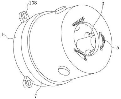
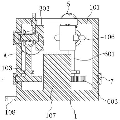
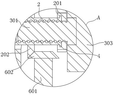
[0034] see Figure 1-9 As shown, the present invention is a centering tool fixture for a numerically controlled machine tool, comprising an outer cylinder 1, a limiting end ring 101 is provided on the inner side of the opening end of the outer cylinder 1; There is a threaded sleeve 2; the inner wall of the end of the threaded sleeve 2 is threadedly connected with a clamping frame 3; the outer wall of the end of the threaded sleeve 2 is provided with a toothed ring ...


PUM


Abstract

The invention discloses a centering tool clamp for a numerically-controlled machine tool, and relates to the technical field of numerically-controlled machine tools. The device comprises an outer cylinder, wherein a limiting end ring is arranged on the inner side of the opening end of the outer cylinder; the inner wall of the outer cylinder is rotationally connected with threaded sleeves; the inner walls of the end parts of the threaded sleeves are in threaded connection with clamping frames; the outer walls of the end parts of the threaded sleeves are sleeved with gear rings; fixing seats arearranged on the inner wall of the outer cylinder in an annular array manner; the tops of the fixing seats are rotationally connected with transmission frames in meshing transmission with the threadedsleeves; and the outer cylinder is rotationally connected with driving gear rings in meshing transmission with the transmission frames through second annular grooves. According to the centering toolclamp for the numerically-controlled machine tool, driving gears are in meshing transmission with the gear rings when rotating, limiting guide blocks on the inner sides of the gear rings cooperate with limiting guide grooves in the circumferential side faces of threaded end rods, and under the limiting effect of guide rods and guide sleeves, the distance of a single clamping frame can be adjusted,an eccentric workpiece can be centered, clamped and fixed, operation is easy, and construction is convenient; and the mounting clamping force is relatively strong, so that actual processing requirements are met.

Description

technical field [0001] The invention belongs to the technical field of numerical control machine tools, in particular to a centering fixture for numerical control machine tools. Background technique [0002] CNC machine tool is a high-precision and high-efficiency automatic machine tool, equipped with multi-station cutting tools, has a wide range of processing performance, and can process complex workpieces such as straight cylinders, oblique cylinders, arcs and box threads, grooves, worms, etc. It has various compensation functions such as linear interpolation and circular interpolation, and has played a good economic effect in the mass production of complex parts. [0003] At present, CNC machine tools generally use chucks to clamp parts such as shafts and pipes. When the disk is locked, when the small bevel gear is pulled with a wrench or a drive motor, the wire will rotate. The flat thread makes the jaws approach or withdraw from the center at the same time. Because of...

Claims


Application Information

Patent Timeline
Patent Type & Authority Applications(China)
IPC IPC(8): B23Q3/12
CPCB23Q3/12
Inventor 冯华王红娟张伟
Owner 五莲完美工具有限公司
Learn More