
Distributed power flow controller injection voltage mode fixed value conversion method and system

A technology of power flow controller and voltage mode, applied in the direction of AC network circuits, electrical components, circuit devices, etc., can solve the problems that only real-time power flow analysis can be carried out, but the power flow analysis of the whole network cannot be carried out.

Active Publication Date: 2021-07-06
ZHEJIANG UNIV +1
View PDF0 Cites 0 Cited by
  • Summary
  • Abstract
  • Description
  • Claims
  • Application Information

AI Technical Summary

Problems solved by technology

[0010] At present, in the actual power grid operation process, when DPFC is controlled according to the injection voltage mode, the impedance is calculated by measuring the DPFC output voltage and line current, but this mode cannot carry out the power flow analysis of the whole network in advance, and can only carry out real-time power flow analysis

Method used


Image

  • Distributed power flow controller injection voltage mode fixed value conversion method and system
  • Distributed power flow controller injection voltage mode fixed value conversion method and system
  • Distributed power flow controller injection voltage mode fixed value conversion method and system

Examples


Embodiment 1

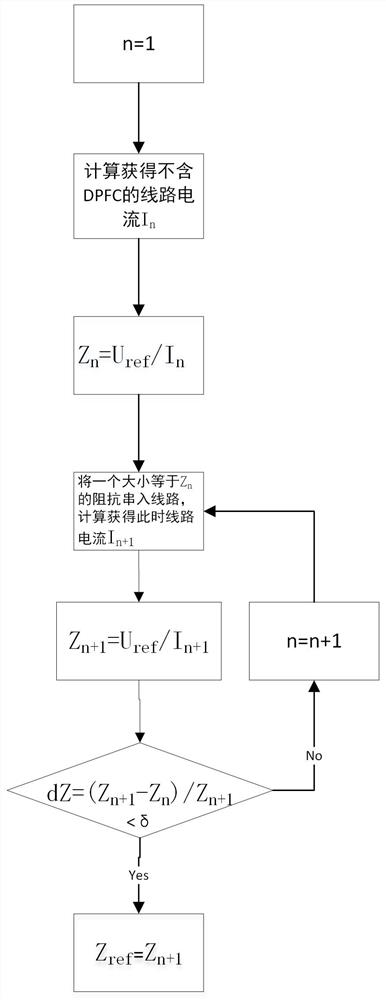
[0038] Such as figure 2 A distributed power flow controller injection voltage mode fixed value conversion method is shown, which converts the voltage control fixed value U ref Convert to Impedance Rating Z ref ,Proceed as follows:

[0039] 1) Set the number of iterations n=1;

[0040] 2) According to the power grid parameters, the line current I without DPFC is calculated by electromechanical transient analysis software n ;

[0041] 3) Calculate Z n =U ref / I n ;

[0042] 4) Set a size equal to Z n According to the new power grid parameters, the new line current I can be obtained by calculating through the electromechanical transient analysis software n+1 ;

[0043] 5) Calculate Z n+1 =U ref / I n+1 ;

[0044] 6) Calculate the impedance difference ratio dZ=(Z n+1 -Z n ) / Z n+1 ;

[0045] 7) Judging the size between dZ and the allowable value of deviation δ, if dZref equal to Z n+1 ; If dZ≥δ, then the number of iterations n=n+1, return to step 4 to continue, Z...

Embodiment 2

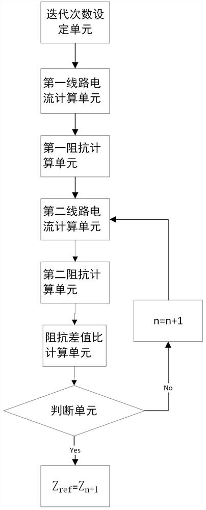
[0048] Such as image 3 The shown distributed power flow controller is injected into the voltage mode fixed value conversion system, which controls the voltage control fixed value U ref Convert to Impedance Rating Z ref , including an iteration number setting unit, a first line current calculation unit, a first impedance calculation unit, a second line current calculation unit, a second impedance calculation unit, an impedance difference calculation unit and a judging unit.

[0049] The number of iterations setting unit, set the number of iterations n=1;

[0050] The first line current calculation unit calculates and obtains the line current I without DPFC through electromechanical transient analysis software according to the grid parameters n ;

[0051] The first impedance calculation unit is used to calculate Z n =U ref / I n ;

[0052]The second line current calculation unit will be a size equal to Z n According to the new power grid parameters, the new line current ...


PUM


Abstract

The invention discloses a fixed value conversion method and system for a distributed power flow controller injection voltage mode. At present, when the distributed power flow controller is controlled by the injection voltage mode, the impedance is calculated by measuring the DPFC output voltage and the line current, but this mode cannot carry out the power flow analysis of the whole network in advance, and can only carry out the real-time power flow analysis. The present invention calculates the impedance of the previous and subsequent two times, and obtains the fixed value of the impedance by judging the difference ratio of the impedance and the allowable value of the deviation. The invention converts the fixed value of the voltage control into the fixed value of the impedance, so that the injected voltage mode can obtain the impedance data through simple calculation, and is suitable for carrying out the power flow analysis of the whole network in advance.

Description

technical field [0001] The invention belongs to the field of distributed power flow controllers, in particular to a fixed value conversion method and system for a distributed power flow controller injection voltage mode. Background technique [0002] DPFC: distributed power flow controller, a power electronic device that changes the line flow by changing the impedance of the series-connected line. Its topology is as follows figure 1 shown. [0003] Fast Bypass Switch (BPS): It consists of a high-speed mechanical bypass switch (K) and an anti-parallel thyristor (TBS) connected in parallel. It is closed when the line does not need to carry out power flow control (small power flow) or when the module is faulty, so as to realize the bypass of the module , open when the line needs to carry out power flow control, and connect the converter in series to the line. [0004] Voltage Source Converter (VSC): The function strobe switch strobes the VSC module, the distributed static ser...

Claims


Application Information

Patent Timeline
Patent Type & Authority Patents(China)
IPC IPC(8): H02J3/00
CPCH02J3/00H02J2203/10
Inventor 裘鹏金玉琪郭锋陆承宇徐华王松陆翌张静潘武略
Owner ZHEJIANG UNIV
Features
  • Generate Ideas
  • Intellectual Property
  • Life Sciences
  • Materials
  • Tech Scout
  • Unparalleled Data Quality
  • Higher Quality Content
  • 60% Fewer Hallucinations
Learn More