
A combined waterproof cover and motor

A waterproof cover, combined technology, applied in the direction of electromechanical devices, electrical components, electric components, etc., can solve the problems of increased resistance of the motor, limited protection effect, and inability to prevent dust and water spray.

Active Publication Date: 2021-10-22
GREE ELECTRIC APPLIANCES INC
View PDF4 Cites 0 Cited by
  • Summary
  • Abstract
  • Description
  • Claims
  • Application Information

AI Technical Summary

Problems solved by technology

In the sealing structure of the motor shaft, contact seals include felt and oil seals. Although the waterproof level can reach IPX5 and above and the effect is reliable, the contact shaft of the seal will increase the resistance of the motor and affect the torque of the motor. Its output speed, power Both are affected, increasing costs; non-contact seals generally use waterproof covers, horizontal ones usually use hard waterproof covers with drip holes installed on the end caps, vertical ones use soft waterproof covers installed on the shaft, and the cost is low And it has no effect on the output of the motor, but the protection effect is limited. Generally, it can reach IP44, but it cannot prevent dust and water spray.

Method used


Image

  • A combined waterproof cover and motor
  • A combined waterproof cover and motor
  • A combined waterproof cover and motor

Examples


Embodiment

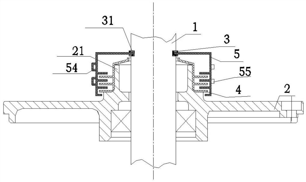
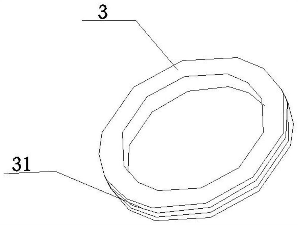
[0044] This embodiment provides a motor which adopts a combined waterproof cover, specifically as follows Figure 1-9 As shown, the combined waterproof cover is used to form a shaft end seal at the end of the rotating shaft 1 of the motor, and the end of the rotating shaft 1 is provided with an end cover 2, and the outer end surface of the end cover 2 is formed with a waterproof boss 21; The waterproof cover includes: a waterproof ring 3, an inner waterproof cover 4 and an outer waterproof cover 5, wherein: the waterproof ring 3 is arranged on the outer wall of the rotating shaft 1 along the circumferential direction of the rotating shaft 1 and rotates with the rotation of the rotating shaft 1; one end of the inner waterproof cover 4 Fitted with the peripheral surface of the rotating shaft 1, the other end is matched with the outer wall surface of the waterproof boss 21, the cover is arranged between the rotating shaft 1 and the waterproof boss 21, and one end of the clearance ...


PUM


Abstract

The invention provides a combined waterproof cover and motor for motor shaft end sealing, and relates to the technical field of motors. The combined waterproof cover includes: a waterproof ring, an inner waterproof cover and an outer waterproof cover, wherein the waterproof ring is along the circumferential direction of the rotating shaft It is arranged on the outer wall of the rotating shaft and rotates with the rotation of the rotating shaft; one end of the inner waterproof cover is in clearance fit with the peripheral surface of the rotating shaft, and the other end is matched with the outer wall of the waterproof boss. One end of the gap fit is formed with a mounting hole for the shaft to pass through, and the inner waterproof cover does not rotate with the rotation of the rotating shaft; the outer waterproof cover is arranged outside the inner waterproof cover, and one end is sealed with the waterproof ring, and the other end is sealed with the inner waterproof cover. The outer waterproof cover can rotate with the rotation of the rotating shaft; interlaced ribs are formed in the gap between the inner waterproof cover and the outer waterproof cover, and the interlaced ribs form a labyrinth waterproof structure. The sealing performance of the sealing structure at the output shaft end of the motor is effectively improved without affecting the output performance of the motor.

Description

technical field [0001] The present invention relates to the technical field of motors, in particular, to a combined waterproof cover and a motor. Background technique [0002] In order to achieve the required protection level, the motor will design a waterproof and dustproof sealing structure, especially the sealing structure of the motor shaft end and the rotating shaft part has always been the key point in the design of the motor protection level. [0003] The sealing structure is divided into a contact sealing structure and a non-contact sealing structure according to the contact relationship between the seal and the parts. In the sealing structure of the motor shaft, the contact seals include felt, oil seal, etc. Although the waterproof level can reach IPX5 or above and the effect is reliable, the contact shaft of the seal will increase the resistance of the motor and affect the torque of the motor, its output speed, power The non-contact seal generally uses a waterproo...

Claims


Application Information

Patent Timeline
Patent Type & Authority Patents(China)
IPC IPC(8): H02K5/10H02K5/124H02K5/04
CPCH02K5/04H02K5/10H02K5/124
Inventor 周思张潮苟小华丁佳婷赵坤所刘丽刚
Owner GREE ELECTRIC APPLIANCES INC
Learn More