Carbon fiber composite material and preparation process thereof
A composite material and preparation process technology, which can be used in other household appliances, slender elements, building elements, etc., and can solve the problem of not being able to combine carbon fiber and other materials to prepare pipes and so on.
- Summary
- Abstract
- Description
- Claims
- Application Information
AI Technical Summary
Problems solved by technology
Method used
Image

Examples
specific Embodiment approach 1
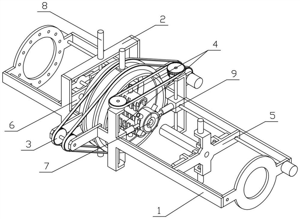
[0036] Combine below Figures 1 to 8 Describe this embodiment, a carbon fiber composite material preparation process, the process includes the following steps:
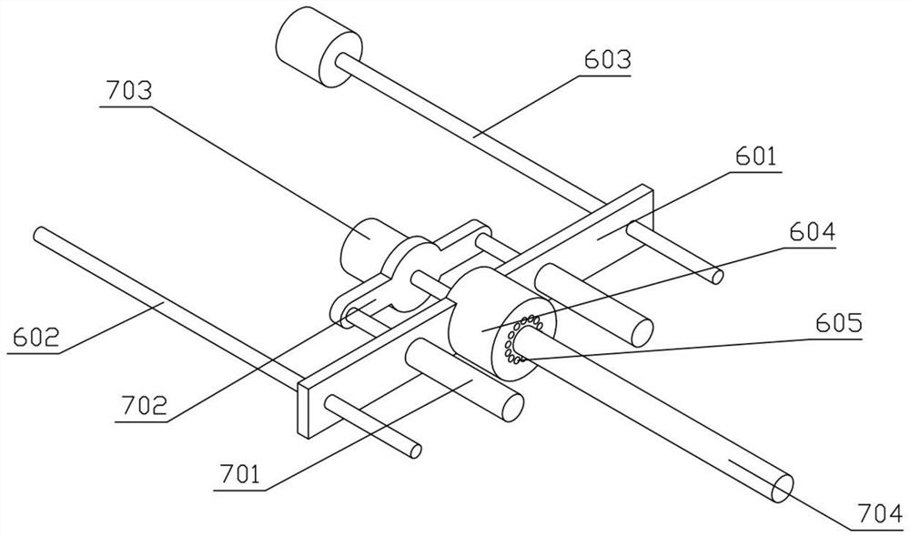
[0037] S1; connect multiple carbon fibers to the pulling mechanism Ⅰ5 through the device bracket Ⅱ2 and the pulling mechanism Ⅱ6;
[0038] S2; Pulling mechanism I5 pulls a plurality of carbon fibers through the space between two injection molding mechanisms 4, the hole-forming mechanism 7 is inserted between the two injection molding mechanisms 4, and the two injection molding mechanisms 4 are closed for injection molding, and the pulling mechanism I5 injects the carbon fiber composite pipe formed by injection molding pull out;
[0039] S3; the cooling mechanism 9 cools the formed carbon fiber composite pipe;
[0040] The above-mentioned carbon fiber composite material preparation process also involves a carbon fiber composite material preparation device. The carbon fiber composite material preparation device includ...
specific Embodiment approach 2
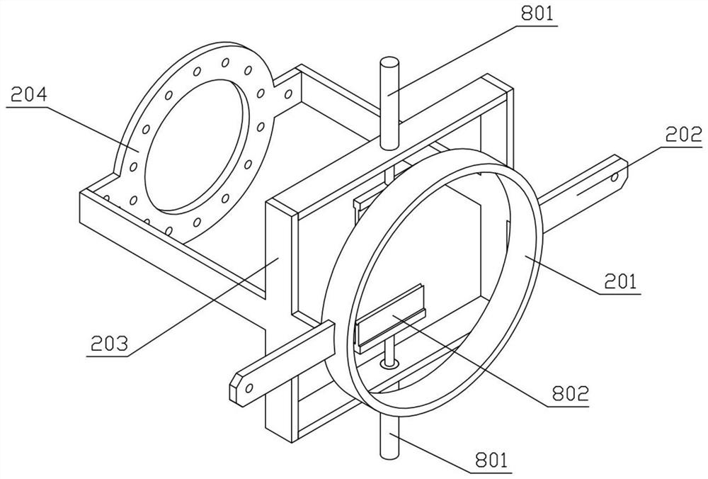
[0042] Combine below Figures 1 to 8 Describe this embodiment, this embodiment will further explain the first embodiment, the device bracket I1 includes the installation ring I101, the support plate I102, the sliding bracket I103 and the connecting ring 104, and the left and right sides of the installation ring I101 are fixedly connected with the support plate Ⅰ102, the two support plates Ⅰ102 are fixedly connected with the sliding bracket Ⅰ103, and the front ends of the two sliding brackets Ⅰ103 are fixedly connected with the connecting ring 104, and the device bracket Ⅱ2 includes the installation ring Ⅱ201, the support plate Ⅱ202, the sliding bracket Ⅱ203 and the limit The ring 204, the left and right sides of the installation ring II 201 are fixedly connected with the support plate II 202, the two support plates II 202 are fixedly connected with the sliding bracket II 203, and the rear ends of the two sliding brackets II 203 are fixedly connected with the limit ring 204. Th...
specific Embodiment approach 3
[0044] Combine below Figures 1 to 8 Describe this embodiment, this embodiment will further explain the second embodiment, the rotating mechanism 3 includes a rotating ring 301, a rotating shaft 302 and a rotating motor 303, the rotating ring 301 is rotatably connected between the installation ring I101 and the installation ring II201, The rotating shaft 302 is rotatably connected between the supporting plate I102 and the supporting plate II202, the rotating shaft 302 and the rotating ring 301 are connected by transmission, the rotating motor 303 is fixedly connected to the supporting plate I102 on one side, the output shaft of the rotating motor 303 and the rotating The shaft 302 is fixedly connected.
PUM
| Property | Measurement | Unit |
|---|---|---|
| Nodule strength | aaaaa | aaaaa |
| Nodule strength | aaaaa | aaaaa |
Abstract
Description
Claims
Application Information
 - R&D Engineer
- R&D Manager
- IP Professional
- Industry Leading Data Capabilities
- Powerful AI technology
- Patent DNA Extraction
Browse by: Latest US Patents, China's latest patents, Technical Efficacy Thesaurus, Application Domain, Technology Topic.
© 2024 PatSnap. All rights reserved.Legal|Privacy policy|Modern Slavery Act Transparency Statement|Sitemap