

A splicing device for CNC machining of square optical elements
An optical element and splicing device technology, applied in optical elements, optics, optical surface grinders, etc., can solve the problems of reducing the stability of the polishing process, affecting the stability of the polishing process, and the loss of polishing liquid, so as to improve the polishing stability and splicing. The effect of low precision requirements and convenient use
Active Publication Date: 2022-06-03
LASER FUSION RES CENT CHINA ACAD OF ENG PHYSICS
View PDF15 Cites 0 Cited by
- Summary
- Abstract
- Description
- Claims
- Application Information
AI Technical Summary
Problems solved by technology
[0003] CNC polishing usually uses cerium oxide polishing fluid to achieve high-precision and ultra-smooth surface processing of optical components, but due to its non-immersion contact polishing characteristics, a large amount of heat generated by the friction between the polishing tool and the surface of the optical component during processing It will cause the local temperature to rise, aggravate the aging speed of the polishing tool, and affect the stability of the polishing process
In addition, under the joint action of the polishing tool rotation and feed movement, the polishing liquid is seriously lost in the corner area of the component, making the concentration of the polishing liquid on the surface of the component unevenly distributed, which further reduces the stability of the polishing process and affects the optical components. Final machining accuracy and machining efficiency
Method used
View moreImage
Smart ImageViewing Examples

Examples
Embodiment Construction
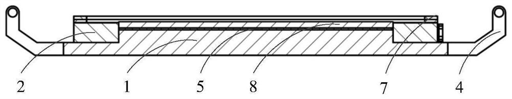
[0028] The area of the silicone pad 5 is equal to the area of the upper boss 11, and the thickness is about 1 mm. The area of tarpaulin 6 is significantly larger than that of the upper boss
[0035] The foregoing description of the disclosed embodiments enables those skilled in the art to make or use the present invention.
Login to View More PUM
 Abstract
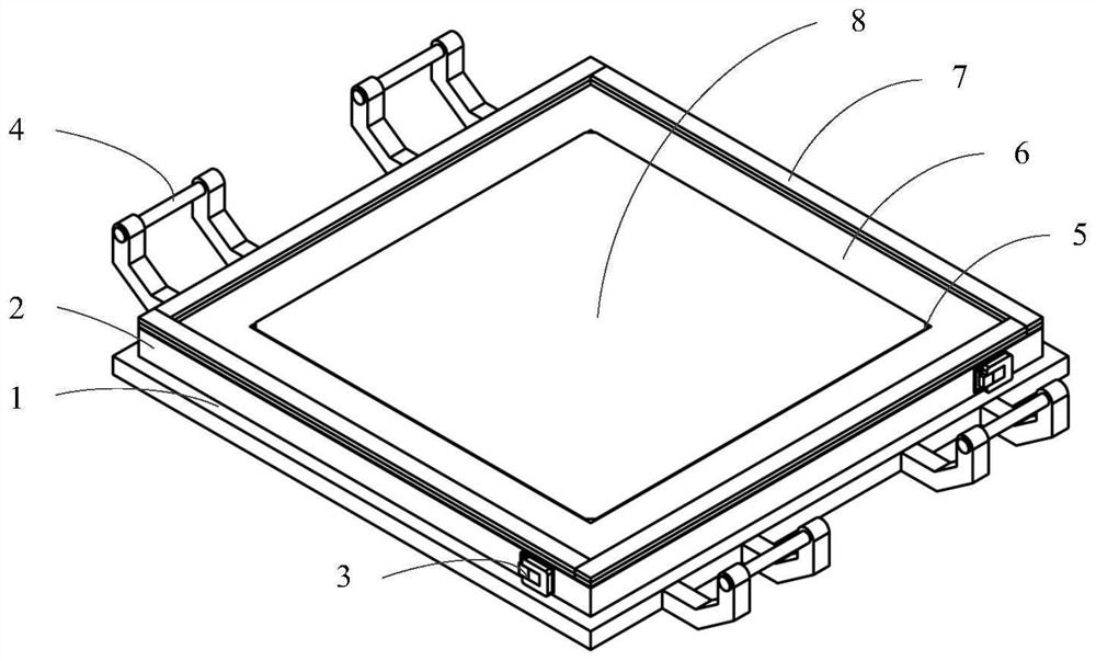
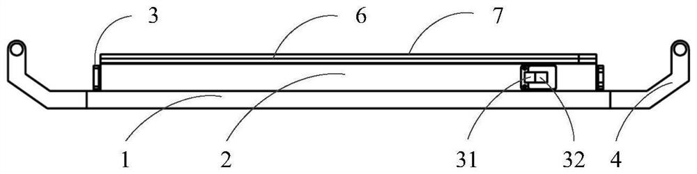
The invention discloses a splicing device for numerically controlled processing of square optical elements, which comprises a square support plate, which is a boss structure, including an upper boss and a lower boss, and the cross-sectional area of the lower boss in the horizontal direction is larger than The upper boss, the area of the upper boss is the same as the optical element to be processed; the upper boss is also provided with a silicone pad and a waterproof cloth in turn; when in use, the optical element to be processed is arranged on the waterproof cloth on; it also includes four splicing blocks, which are connected to each other and arranged above the lower boss for clamping the optical element to be processed on the upper boss, the upper of the optical element to be processed The surface is slightly higher than the upper surface of each splicing block, and several magnetic strips for fixing the waterproof cloth are arranged on the outside of the top surface of each splicing block. The above-mentioned splicing device has two functions of component clamping and polishing liquid storage at the same time, which realizes immersion polishing of components and improves the polishing stability of components.
Description
A splicing device for CNC machining of square optical components technical field The present invention relates to the technical field of optical processing, particularly a kind of splicing for the numerical control processing of square optical elements device. Background technique With the development of high-power laser devices, telescope systems, aerospace and ultraviolet lithography and other fields, the The number of demand for scientific components is increasing, and the requirements for component processing accuracy and processing efficiency are also getting higher and higher. Gadget CNC The polishing technology precisely controls the rotational speed of the polishing tool, the processing path and the processing points of the polishing tool on the surface of the component through the computer Compared with full-aperture polishing techniques such as ring polishing, it can achieve a deterministic increase in the surface material of optical components. It is th...
Claims
Login to View More Application Information
Patent Timeline
 Patent Type & AuthorityPatents(China)
IPC IPC(8): B24B13/00B24B13/005
CPCB24B13/00B24B13/0055
Inventor黄金勇高胥华蔡超王刚谢磊赵恒胡庆何祥马平鄢定尧李瑞洁
OwnerLASER FUSION RES CENT CHINA ACAD OF ENG PHYSICS