Piezoelectric conductor ceramic clamping fixture

A technology for clamping fixtures and conductors, applied in workpiece clamping devices, manufacturing tools, etc., to solve problems such as shaking, unstable clamping of piezoelectric conductor ceramics, and small contact area.

Inactive Publication Date: 2021-03-23
韩志刚
View PDF0 Cites 2 Cited by
  • Summary
  • Abstract
  • Description
  • Claims
  • Application Information

AI Technical Summary

Problems solved by technology

[0003] Since the clamping plates on both sides of the clamping fixture for piezoelectric conductor ceramics are flat, if the piezoelectric conductor ceramics with a curved surface is clamped between the clamping plates, it is easy to be caused by the gap between the clamping plate and the piezoelectric conductor ceramics. The contact area is small, resulting in unstable clamping of piezoelectric conductor ceramics, shaking or even falling

Method used


Image

  • Piezoelectric conductor ceramic clamping fixture
  • Piezoelectric conductor ceramic clamping fixture
  • Piezoelectric conductor ceramic clamping fixture

Examples


Embodiment 1

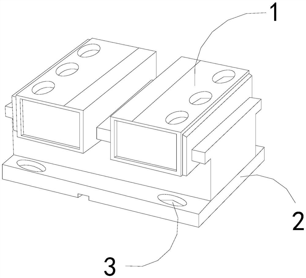
[0026] For example figure 1 -example Figure 5 Shown:

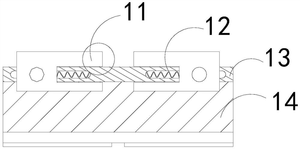
[0027] The present invention provides a clamping fixture for piezoelectric conductor ceramics, the structure of which includes a fixing mechanism 1, a bottom plate 2, and a connecting hole 3, the connecting hole 3 and the bottom plate 2 are an integrated structure, and the fixing mechanism 1 is embedded in the bottom plate 2 The upper end position; the fixing mechanism 1 includes a clamping plate 11, a power strip 12, a guide plate 13, and a bottom plate 14, the clamping plate 11 is movably engaged with the guide plate 13, and the power strip 12 is installed on the guide plate 13 and the bottom plate 14. Between the clamping plates 11, the guide plate 13 and the bottom plate 14 are an integrated structure.

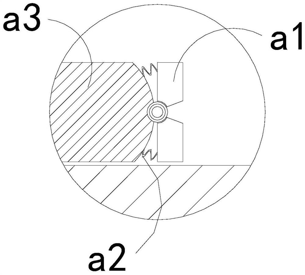
[0028] Wherein, the clamping plate 11 includes a front plate a1, a connecting bar a2, and a bottoming plate a3, the front plate a1 is hinged to the right side of the bottoming plate a3, and the connecting bar a2 is ...

Embodiment 2

[0034] For example Figure 6 -example Figure 8 Shown:

[0035] Wherein, the grip groove b2 includes a stabilizing bar b21, an inner connecting plate b22, a bearing plate b23, and a deformation block b24. The stabilizing bar b21 is embedded in the right side of the inner connecting plate b22, and the inner connecting plate b22 The deformed block b24 is connected to the bearing plate b23, and the deformed block b24 is made of polyether sponge material with high density, and the deformed block b24 can be reset by the deformed block b24.

[0036] Wherein, the stabilizing bar b21 includes an outer push piece c1, a combination block c2, and an outer expansion plate c3, and the outer push piece c1 is installed between two outer expansion plates c3, and the outer expansion plate c3 and the combination block c2 are movable There are two outer expansion plates c3, which are evenly distributed symmetrically at the upper and lower ends of the joint block c2, and the outer expansion pla...


PUM


Abstract

The invention discloses a piezoelectric conductor ceramic clamping fixture. The fixture structurally comprises a fixing mechanism, a bottom plate and connecting holes, wherein the connecting holes andthe bottom plate are of an integrated structure, and the fixing mechanism is fixed to the upper end of the bottom plate in an embedded mode. According to the fixture, front swing plates can swing forwards along a rear plate through thrust generated by the surface of piezoelectric conductor ceramic to the front swing plates, so that gripping grooves can generate gripping force to the piezoelectricconductor ceramic, front plates can clamp the piezoelectric conductor ceramic with radian on the surface, and the situation that the piezoelectric conductor ceramic shakes and even falls off when clamping plates clamp the piezoelectric conductor ceramic with the radian on the surface is effectively avoided; and outer pushing pieces can expand outwards along combination blocks through thrust generated by the inner walls of grooves of the piezoelectric conductor ceramic to the two outer pushing pieces, so that the outer surfaces of attaching plates can be attached to the inner walls of the grooves of the piezoelectric conductor ceramic in cooperation with outer pushing strips.

Description

technical field [0001] The invention relates to the field of conductor ceramics, in particular to a clamping fixture for piezoelectric conductor ceramics. Background technique [0002] The piezoelectric conductor ceramic clamping fixture is mainly used for clamping the piezoelectric conductor ceramics. By placing the piezoelectric conductor ceramics between two clamping plates, the piezoelectric conductor ceramics are clamped by the clamping plate. Based on the above description, the inventors found that the existing clamping fixture for piezoelectric conductor ceramics mainly has the following deficiencies, for example: [0003] Since the clamping plates on both sides of the clamping fixture for piezoelectric conductor ceramics are flat, if the piezoelectric conductor ceramics with a curved surface is clamped between the clamping plates, it is easy to be caused by the gap between the clamping plate and the piezoelectric conductor ceramics. The contact area is small, result...

Claims


Application Information

Patent Timeline
Patent Type & Authority Applications(China)
IPC IPC(8): B25B11/00
CPCB25B11/00
Inventor 韩志刚
Owner 韩志刚
Why Eureka
Try Eureka