
Cast-in-place stand column in civil construction and construction method thereof

A technology of civil architecture and columns, which is applied to the preparation of building components on site, construction, and building construction. It can solve the problems of difficult transportation of formwork, affecting construction quality, and deformation of columns, and achieves strong practicability and is easy to disassemble and transport. , The effect of firm connection and strong shape

Inactive Publication Date: 2021-03-30
ZHEJIANG OCEAN UNIV
View PDF6 Cites 0 Cited by
  • Summary
  • Abstract
  • Description
  • Claims
  • Application Information

AI Technical Summary

Problems solved by technology

[0004] The above-mentioned technical solution solves the problem of supporting the cast-in-place column and using a detachable structure to a certain extent to solve the problem that the existing formwork is relatively large and difficult to transport, but it has the following defects: 1. It uses multiple plate-like structure foundations The slabs form a ring structure, connected by connecting blocks, and tied tightly with steel wire ropes during use. The above scheme is prone to expansion in actual pouring. The structure is extruded, and the steel wire rope used for binding is a non-rigid structure. Therefore, under the action of concrete pressure, the ring structure will bulge outwards, which will cause the column to deform and affect the quality of the column; 2. Each foundation plate depends on each other In the actual pouring, if there is a slight error between each foundation slab, the concrete grout will flow out from the gap between the foundation slabs, which will affect the construction quality and cause waste of concrete

Method used


Image

  • Cast-in-place stand column in civil construction and construction method thereof
  • Cast-in-place stand column in civil construction and construction method thereof
  • Cast-in-place stand column in civil construction and construction method thereof

Examples


Embodiment Construction

[0041] The following will clearly and completely describe the technical solutions in the embodiments of the present invention with reference to the accompanying drawings in the embodiments of the present invention. Obviously, the described embodiments are only some, not all, embodiments of the present invention. Based on the embodiments of the present invention, all other embodiments obtained by persons of ordinary skill in the art without making creative efforts belong to the protection scope of the present invention.

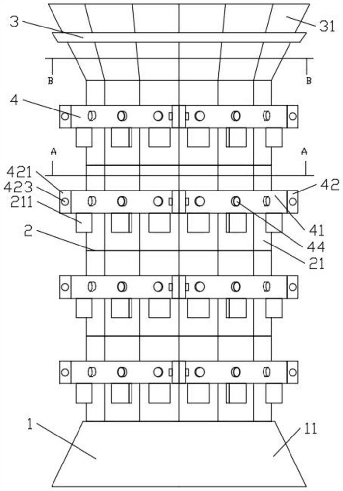
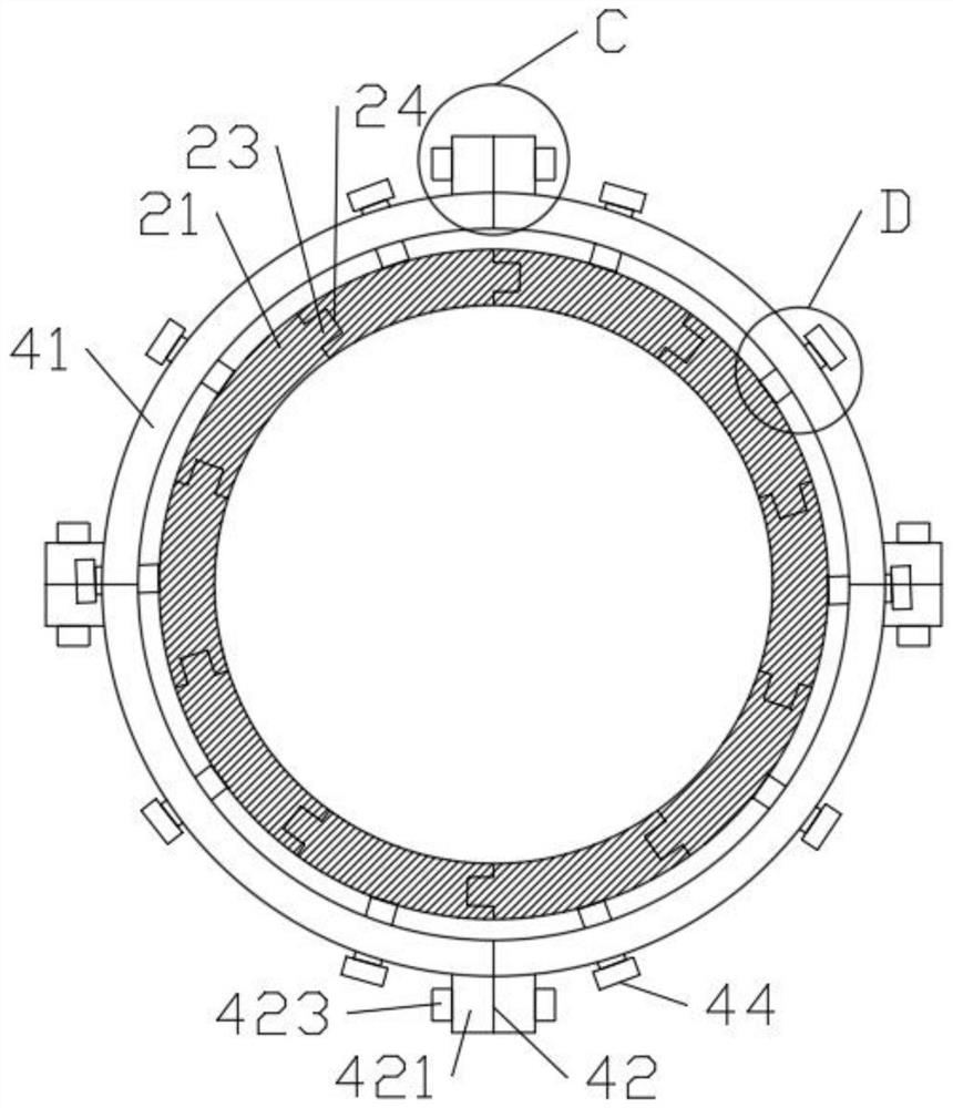
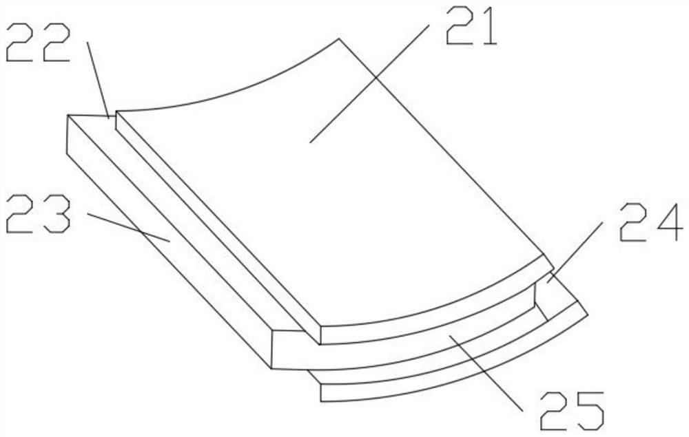
[0042] see Figure 1-8 , the present invention provides a technical solution: a cast-in-place column in civil engineering, including a base unit 1, a combined column unit 2, a top feeding unit 3, and a tightening unit 4, and the combined column unit 2 is inserted and installed on On the base unit 1, the top feeding unit 3 is installed above the combined column unit 2, and the clamping unit 4 is set outside the combined column unit 2, and the base unit 1, the c...


PUM


Abstract

The invention discloses a cast-in-place stand column in civil construction and a construction method thereof, and belongs to the field of civil construction. The cast-in-place stand column comprises abase unit, a combined column body unit, a top feeding unit and a hooping unit, wherein the combined column body unit is installed on the base unit in an inserted mode, the top feeding unit is installed above the combined column body unit, and the hooping unit sleeves the outside the combined column body unit. According to the cast-in-place stand column, the stand column which needs to be poured is supported through the base unit, the combined column body unit, the top feeding unit and the hooping unit, all of the units are of a separated assembly structure and are convenient to disassemble and transport, gaps of all structural parts on the combined column body unit are reduced in a clamping mode that grooves and bulges are matched, and the connection firmness is high, so that the problemthat concrete overflows from the gaps is solved, and the problem that a formwork bulges due to the pressure of concrete in a pouring process is solved through surrounding type hooping of the hooping unit.

Description

technical field [0001] The invention relates to the field of civil construction, in particular to a cast-in-situ column in civil construction and a construction method thereof. Background technique [0002] With the rapid development of my country's economic construction, a large number of urban high-rise buildings have emerged, and the requirements for civil engineering projects are also getting higher and higher. With the continuous development of civil engineering, buildings with cast-in-place structures have become the main trend in today's construction industry. In the construction of existing civil engineering buildings, support columns need to be poured. For existing cast-in-place support columns, large-scale formwork is often used for support, and the transportation and installation of large formwork are difficult. [0003] In the prior art, the patent with the patent authorization announcement number CN106760507B has announced a technical solution: including: a fee...

Claims


Application Information

Patent Timeline
Patent Type & Authority Applications(China)
IPC IPC(8): E04G13/02
CPCE04G13/021
Inventor 杜珈宇黄宝涛
Owner ZHEJIANG OCEAN UNIV
Learn More