Relay

A relay, fixed contact technology, applied in relays, electromagnetic relays, electromagnetic relay details, etc., can solve problems such as movement of difficult-to-move parts

Pending Publication Date: 2021-03-30
ORMON CORP
View PDF1 Cites 0 Cited by
  • Summary
  • Abstract
  • Description
  • Claims
  • Application Information

AI Technical Summary

Problems solved by technology

However, if the movable contact piece becomes heav...

Method used


Image

  • Relay
  • Relay
  • Relay

Examples


Embodiment Construction

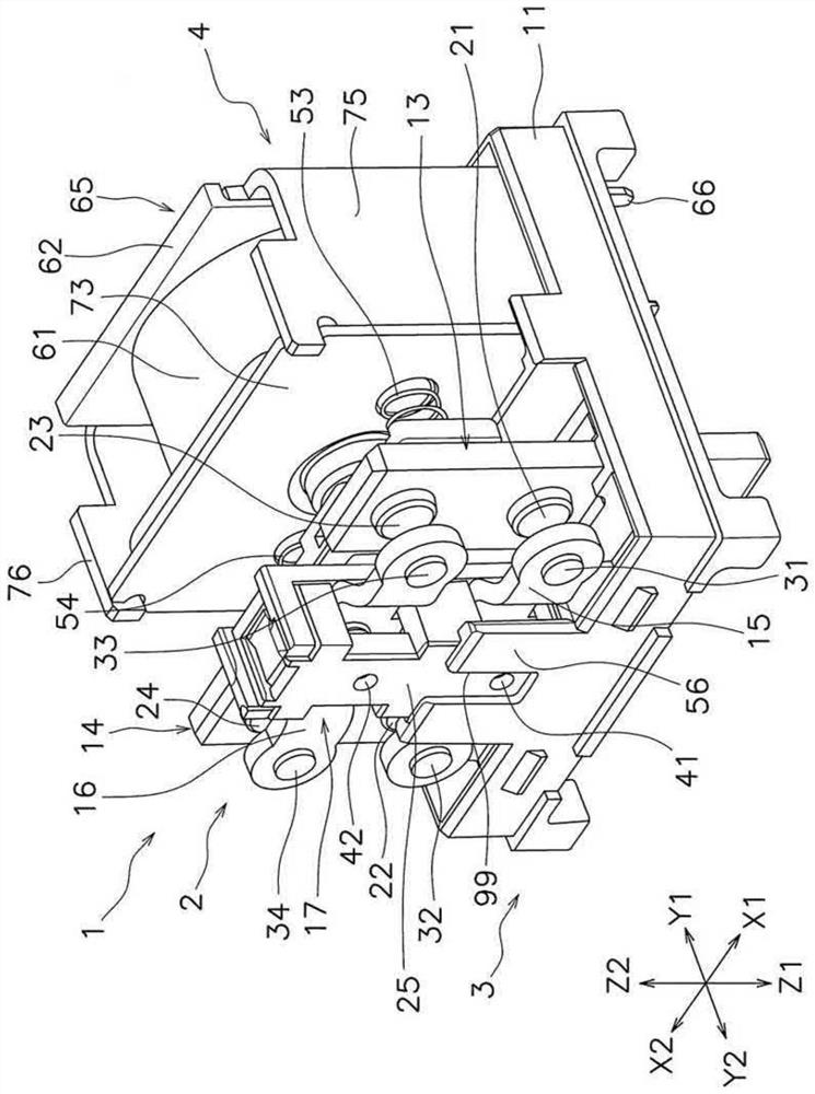
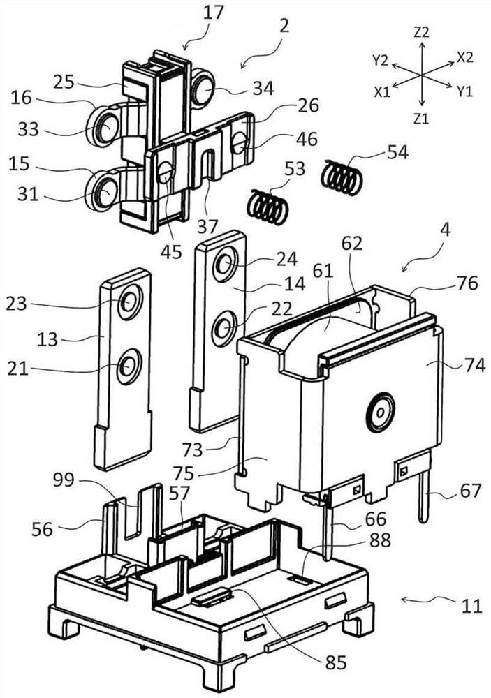
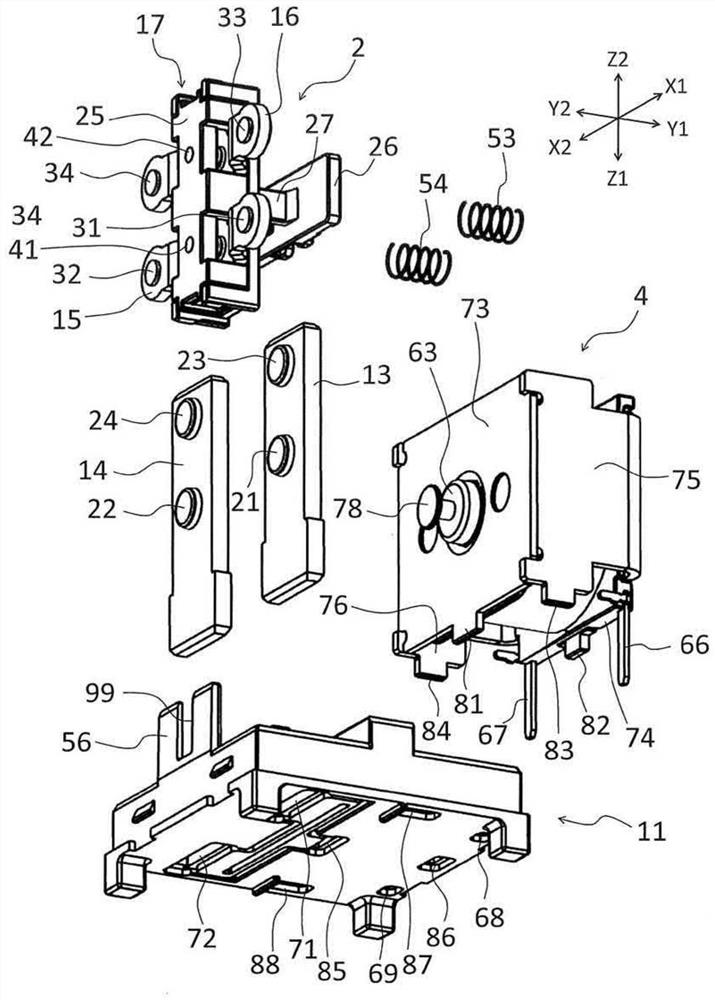
[0026] Next, a relay according to an embodiment will be described with reference to the drawings. figure 1 It is a perspective view of the relay 1 of embodiment. figure 2 with image 3 It is an exploded perspective view of relay 1. Figure 4 is a longitudinal sectional view of the relay 1. Figure 5 with Image 6 is a top view of relay 1.

[0027] The relay 1 includes a contact assembly 2 , a housing 3 , a coil assembly 4 , a first fixed terminal 13 and a second fixed terminal 14 . The contact assembly 2 and the coil assembly 4 are arranged in the housing 3 . The housing 3 includes a base 11 and a box 12 . The base 11 and the case 12 are made of resin, for example. In addition, in figure 1 Among them, the box body 12 is omitted. The base 11 supports the first fixed terminal 13 , the second fixed terminal 14 , the contact assembly 2 and the coil assembly 4 .

[0028] In this embodiment, the movement direction (Y1, Y2), the support direction (Z1, Z2), and the lateral ...


PUM


Abstract

In a relay according to the present invention, a moving member includes a support portion that holds a movable contact piece. A base includes a bottom surface and a first wall portion. The first wallportion extends from the bottom surface in the supporting direction and faces the moving member in the moving direction. At least a part of the first wall portion overlaps with the movable iron core when viewed from the moving direction.

Description

technical field [0001] The invention relates to a relay. Background technique [0002] The relay has a pair of fixed terminals, a movable contact piece, and a moving member (for example, refer to Japanese Patent Application Laid-Open No. 2002-042626). Fixed contacts are connected to the fixed terminals. The movable contact piece is connected with the movable contact. The moving part supports the movable contact piece. The movable contact piece moves together with the moving part, so that the movable contact and the fixed contact are opened or closed. [0003] In the above-mentioned relay, by stably moving the movable member, it is possible to stably open and close the movable contact and the fixed contact. However, if the movable contact piece becomes heavy, it will be difficult to move the moving member stably. Contents of the invention [0004] An object of the present invention is to improve the stability of the operation of a relay by stably moving a moving member...

Claims


Application Information

Patent Timeline
IPC IPC(8): H01H50/64H01H50/04
CPCH01H50/642H01H50/041H01H50/546H01H50/045H01H50/08H01H1/0015H01H49/00
Inventor 三宅彩加松岛弘一郎小材裕二
Owner ORMON CORP
Why Eureka
Try Eureka