
Bidirectional rapid tunneling device and method suitable for simulating construction from transverse tunnel to main tunnel

A horizontal hole and front hole technology, which is applied to mining equipment, earth square drilling, mining equipment, etc., can solve the problems of slag discharge, inconvenient excavation, over-excavation and under-excavation, and labor-intensive problems of the ultra-long tunnel experimental model, and achieve real-time Detect displacement and deformation in the hole, improve efficiency and excavation speed, and save time

Active Publication Date: 2021-04-06
SHANDONG UNIV
View PDF8 Cites 1 Cited by
  • Summary
  • Abstract
  • Description
  • Claims
  • Application Information

AI Technical Summary

Problems solved by technology

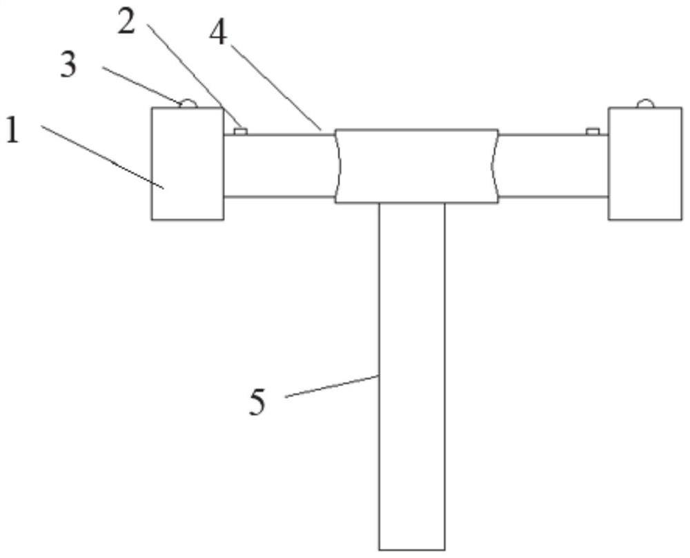
[0004] The inventors have found that in the general excavation process of the tunnel experimental model, shovels or cutters are usually used for manual excavation. The traditional excavation method has the following defects: 1) time-consuming; 2) labor-intensive: when used in the experiment When the experimental model of the tunnel is too long, multiple people need to take turns to excavate; 3) In the face of excavating a long tunnel, the inconvenient excavation will lead to over-excavation and under-excavation; 4) The slag discharge problem of the ultra-long tunnel experimental model

Method used


Image

  • Bidirectional rapid tunneling device and method suitable for simulating construction from transverse tunnel to main tunnel
  • Bidirectional rapid tunneling device and method suitable for simulating construction from transverse tunnel to main tunnel
  • Bidirectional rapid tunneling device and method suitable for simulating construction from transverse tunnel to main tunnel

Examples


Embodiment Construction

[0043] The present invention will be further described below in conjunction with the accompanying drawings and embodiments.

[0044] It should be noted that the following detailed description is exemplary and intended to provide further explanation of the present invention. Unless defined otherwise, all technical and scientific terms used herein have the same meaning as commonly understood by one of ordinary skill in the art to which this invention belongs.

[0045] It should be noted that the terminology used here is only for describing specific embodiments, and is not intended to limit exemplary embodiments according to the present invention. As used herein, unless the context clearly dictates otherwise, the singular is intended to include the plural, and it should also be understood that when the terms "comprising" and / or "comprising" are used in this specification, they mean There are features, steps, operations, means, components and / or combinations thereof.

[0046] In...


PUM


Abstract

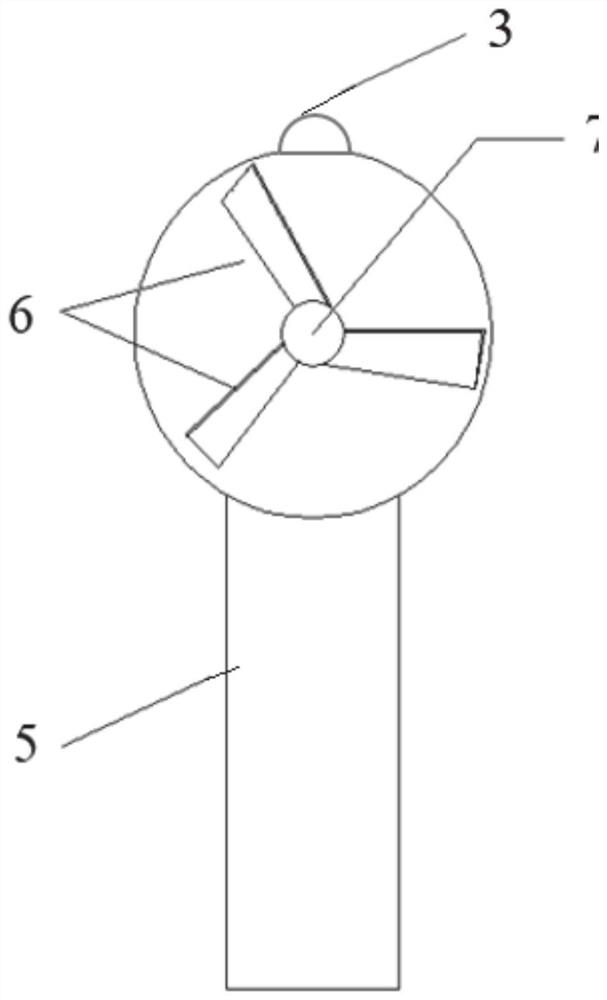
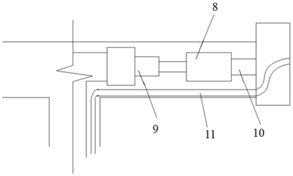
The invention provides a bidirectional rapid tunneling device and method suitable for simulating construction from a transverse tunnel to a main tunnel. The bidirectional rapid tunneling device comprises a cutting part, a video monitoring part, an in-tunnel deformation monitoring part and an operation platform, wherein the cutting part of the device is used for carrying out bidirectional excavation on the main tunnel through the transverse tunnel; the video monitoring part is used for converting a tunnel internal excavation video into continuous frames of tunnel internal images, extracting a tunnel excavation section of each frame of tunnel internal images, comparing the tunnel excavation sections with a pre-designed excavation contour line position, and monitoring the excavation condition in the tunnel in real time so as to prevent the tunnel from being overexcavated and underexcavated; the in-tunnel deformation monitoring part is used for collecting tunnel contour features in the tunnel construction process in real time and comparing the tunnel contour features with a tunnel contour feature library pre-stored in the in-tunnel deformation monitoring part to achieve real-time monitoring of in-tunnel deformation displacement in the excavation process; and the operation platform is connected with the cutting part, the video monitoring part and the in-tunnel deformation monitoring part and used for controlling the advancing mode of the cutting part.

Description

technical field [0001] The invention belongs to the field of tunnel construction, and in particular relates to a two-way rapid tunneling device and method suitable for simulating the construction from a transverse tunnel to a main tunnel. Background technique [0002] The statements in this section merely provide background information related to the present invention and do not necessarily constitute prior art. [0003] my country has a vast territory and complex geological conditions. The geological and engineering conditions of tunnels under construction are becoming more and more complex, and the problems in the construction of extra-long tunnels in complex environments are becoming more and more prominent. [0004] The inventors found that in the general excavation process of the tunnel experimental model, a shovel or a cutter is usually used for manual excavation. The traditional excavation method has the following defects: 1) time-consuming; 2) labor-intensive: when u...

Claims


Application Information

Patent Timeline
IPC IPC(8): E21D9/00E21D9/10E21D9/13E21D9/14E21F17/18
CPCE21D9/003E21D9/10E21D9/1006E21D9/104E21D9/1093E21D9/13E21D9/14E21F17/18
Inventor 石少帅孙昊政吴琪孙子正李术才郭伟东张涛王康赵瑞杰
Owner SHANDONG UNIV
Learn More