Shifter system with variable shifting force

A shifter and gear force technology, which is applied in the testing of instruments, components with teeth, and mechanical components, etc., can solve problems such as difficulty in shifting force, reduce time and cost, save development cycle, and conform to platformization and intelligent effects

Pending Publication Date: 2021-04-09
GAC COMPONENT CO LTD
View PDF7 Cites 0 Cited by
  • Summary
  • Abstract
  • Description
  • Claims
  • Application Information

AI Technical Summary

Problems solved by technology

Because drivers are accustomed to different gear shifting forces, it is difficult to adjust to all drivers and cannot meet the needs of all drivers, so the calibration of gear shifting force has always been a difficult problem

Method used


Image

  • Shifter system with variable shifting force
  • Shifter system with variable shifting force
  • Shifter system with variable shifting force

Examples


Embodiment Construction

[0025] Below, the present invention will be further described in conjunction with the accompanying drawings and specific implementation methods. It should be noted that, under the premise of not conflicting, the various embodiments described below or the technical features can be combined arbitrarily to form new embodiments. .

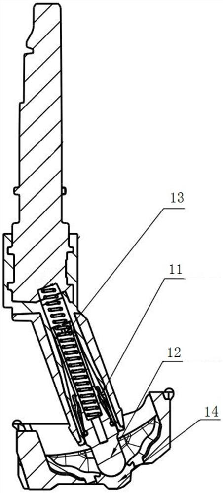
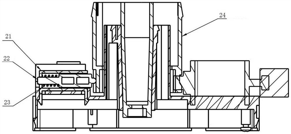
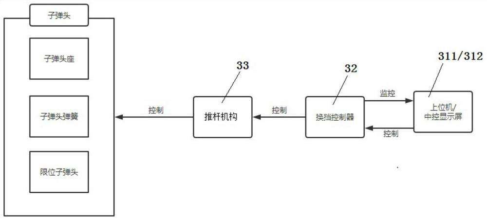
[0026] combine Figure 3 to Figure 5 , a shifter system with variable gear force, including a host computer 311, a shift controller 32, a push rod mechanism 33, a bullet and a shift sense module 14 or a knob body 24, wherein the shift sense module 14 Corresponds to the pushrod shifter (see Figure 4 ), the knob body 24 corresponds to the knob type shifter (see Figure 5 ), the bullet structure and principle of the push rod type shifter and the knob type shifter are basically the same.

[0027] See image 3 , the host computer 311 is connected to the shift controller 32 through an emulator (not shown), and the shift controller 32 is electrically con...


PUM


Abstract

The invention discloses a shifter system with variable shifting force. The shifter system comprises an upper computer, a shifting controller, a push rod mechanism, a bullet and a shifting sensing module/knob body, wherein the upper computer is connected to the shifting controller through a simulator; the shifting controller is electrically connected to the push rod mechanism; the bullet comprises a bullet seat, a bullet spring and a limiting bullet; the limiting bullet is used for being in contact with the shifting sensing module/knob body; and the push rod mechanism is used for compressing/releasing the bullet spring in order to adjust the interaction force between the limiting bullet and the shifting sensing module/knob body. The shifter system gives a driver a personalized shifting force defining way, so that the product is more popular, humanized and intelligent.

Description

technical field [0001] The invention relates to the technical field of shifters, in particular to a shifter system capable of shifting gear force. Background technique [0002] Push-rod electronic shifters and knob-type electronic shifters are now the mainstream products of automotive shifters. In addition to the wire control program, the shifting force is also an important indicator to measure whether a shifter meets the user's requirements. one. [0003] Such as figure 1 As shown, the shifting force of the pushrod shifter is mainly determined by the structure composed of the bullet base 11, the limit bullet 12, the bullet spring 13 and the shift feeling module 14, which is mainly determined by the spring stiffness. It will take a lot of time to verify the adjustment, and when the spring stiffness is confirmed, the shift force will be determined and cannot be adjusted, and there is no individualized condition. The specific structure of the push rod shifter can refer to t...

Claims


Application Information

Patent Timeline
Patent Type & Authority Applications(China)
IPC IPC(8): F16H59/02G01L5/00G01M13/025
CPCF16H59/02G01L5/0061G01M13/025
Inventor 陈杰彬黄锐景谢光胡锡胜于文函
Owner GAC COMPONENT CO LTD
Why Eureka
Try Eureka