Power cable connector and connecting method thereof

A power cable and connector technology, which is applied in the field of power cable connectors and their connections, can solve problems such as cable looseness, overheating of cable connectors, and fires, and achieve the effects of preventing cable loosening, facilitating wiring, and reducing potential safety hazards

Inactive Publication Date: 2021-04-13
王刚
View PDF7 Cites 3 Cited by
  • Summary
  • Abstract
  • Description
  • Claims
  • Application Information

AI Technical Summary

Problems solved by technology

[0004] This application proposes a power cable connector and its connection method, which aims to solve the problem of loosening and sparking of the cable connected at the cable connector in the prior art, which has potential safety risks. At the same time, the cable The connection head is prone to overheating, which may cause equipment failure or fire problems

Method used


Image

  • Power cable connector and connecting method thereof
  • Power cable connector and connecting method thereof
  • Power cable connector and connecting method thereof

Examples


Embodiment 1

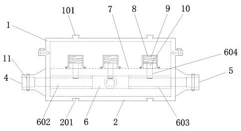
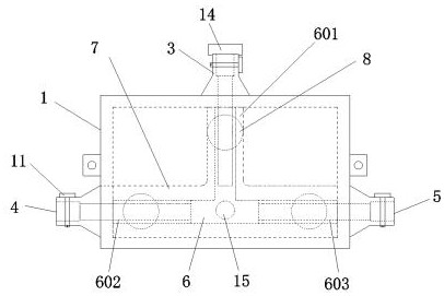
[0029] A power cable connector such as Figure 1 to Figure 2 As shown, it includes a housing, a wiring module and a crimping module, the wiring module is installed inside the housing, and the crimping module is installed on the wiring module; the housing includes an upper housing 1 and a lower housing 2, The upper casing 1 is connected with the lower casing 2 by bolts; the front side wall of the lower casing 2 is provided with an upper wire inlet 3, the left side of the lower casing 2 is provided with a left wire inlet 4, and the right side of the lower casing 2 A right wire inlet 5 is provided; the wiring module includes a terminal 6, the terminal 6 is covered with a sheath 7, and the terminal 6 includes an upper terminal 601, a left terminal 602 and a right terminal 603, and the upper terminal 601 Connected with the upper wire inlet 3, the left wire inlet 602 is connected with the left wire inlet 4, and the right wire inlet 603 is connected with the right wire inlet 5; The ...

Embodiment 2

[0036] A power cable connector such as figure 1 As shown, the top surface of the upper housing 1 is provided with a pin 101, and the bottom surface of the lower housing 2 is provided with a slot 201, which can realize the splicing of multiple cable connectors, ensure the neatness of the wiring, and facilitate the heat dissipation of the cables.

[0037]It can further be that semi-circular grooves are provided on the upper and lower contact surfaces of the upper housing 1 and the lower housing 2, and the two semi-circular grooves form a circular groove, and a sealing ring is installed in the circular groove to play a better sealing effect. , to achieve waterproof function.

[0038] It can be further, such as Figure 4 As shown, the side walls of the upper wire inlet 3, the left wire inlet 4 and the right wire inlet 5 are respectively provided with a sliding groove 12 and a locking hole 13, and a locking clip 11 is installed on the sliding groove 12 and the locking hole 13, and...


PUM


Abstract

The invention discloses a power cable connector and a connection method thereof, the connector comprises a shell, a wiring module and a wire pressing module, the wiring module is installed in the shell, and the wire pressing module is installed on the wiring module; the shell comprises an upper shell and a lower shell, an upper wire inlet is formed in the front side wall of the lower shell, a left wire inlet is formed in the left side of the lower shell, and a right wire inlet is formed in the right side of the lower shell; the wiring module comprises a binding post, the binding post is sleeved with a sheath, and the binding post comprises an upper wiring port, a left wiring port and a right wiring port. The connector compresses a cable through the cable pressing module, the cable is prevented from exiting through a locking clamp, the automatic locking function is achieved, the cable loosening problem caused by vibration is prevented, the binding post is of a T-shaped binding post structure, the multi-direction connection of the cable can be achieved, power cable wiring is more convenient, and a temperature measuring device is used for monitoring the temperature of a cable joint and providing an alarm, thereby reducing potential safety hazards.

Description

technical field [0001] The present application relates to the technical field of power cables, in particular to a power cable connector and a connection method thereof. Background technique [0002] Power cables are cables used to transmit and distribute electric energy. Power cables are often used in urban underground power grids, outgoing lines of power stations, internal power supply of industrial and mining enterprises, and underwater transmission lines across rivers and seas. In power lines, the proportion of cables is gradually increasing. Power cables are cable products used to transmit and distribute high-power electric energy in the backbone lines of power systems, including various voltage levels of 1500KV and above. [0003] In the process of cable construction, it is necessary to use connectors to connect two sections of cables. In some factories, the cables need to be arranged near the equipment. Due to the long-term vibration of the equipment, the cables connec...

Claims


Application Information

Patent Timeline
Patent Type & Authority Applications(China)
IPC IPC(8): H02G15/10H02G1/14
CPCH02G15/10H02G1/14
Inventor 王刚
Owner 王刚
Why Eureka
Try Eureka