Oblique synchronous distance adjusting mechanism for aluminum pipe fitting production
An adjustment mechanism and a technology for aluminum pipe fittings, which are applied in the field of oblique synchronous spacing adjustment mechanisms for the production of aluminum pipe fittings
- Summary
- Abstract
- Description
- Claims
- Application Information
AI Technical Summary
Problems solved by technology
Method used
Image

Examples
Embodiment Construction
[0060] In order to make the objects and advantages of the present invention clearer, the present invention will be described in detail below in conjunction with the examples. It should be understood that the following words are only used to describe one or several specific implementation modes of the present invention, and do not strictly limit the protection scope of the specific claims of the present invention.
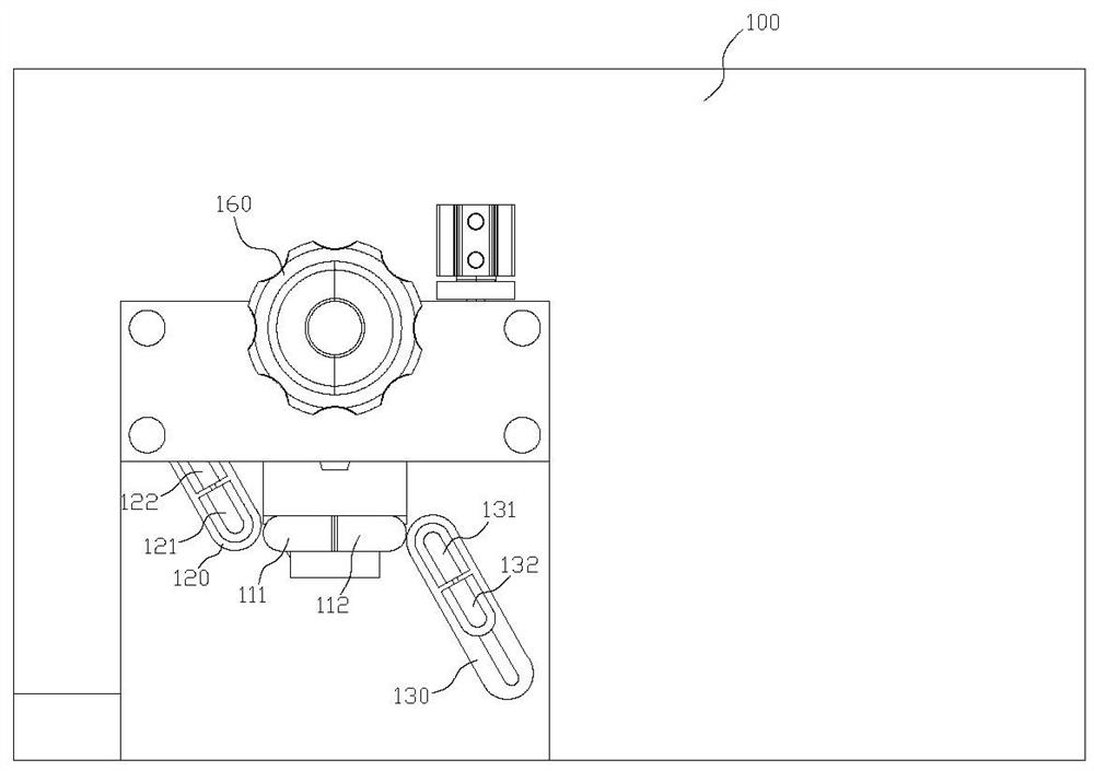
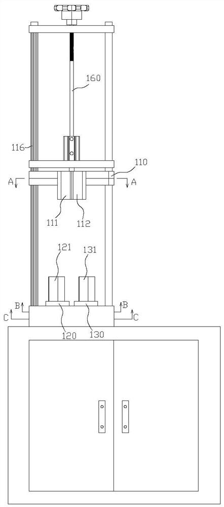
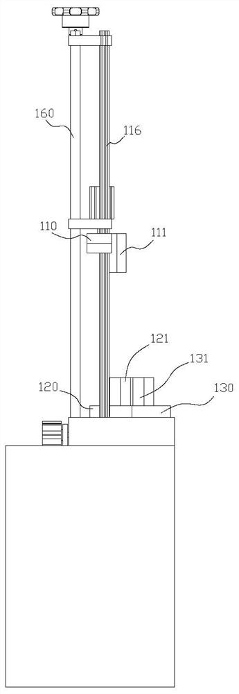
[0061] refer to Figure 1 to Figure 7 As shown, an aluminum tube folding machine includes a folding frame 100, and the folding frame 100 is provided with A and B folding mechanisms correspondingly arranged up and down. A detour, note that the two detours adjacent to A detour on the aluminum tube are B1 and B2 detours, A detour and B1, B2 detour are located at both ends of the twisted aluminum pipe, and the A half-folding mechanism has a function for Fix the A fixing part at the detour of A, the A fixing part has the A fixing port to accommodate the A detour, the B ...
PUM
 Abstract
Description
Claims
Application Information