Plaster bandage folding machine

A plaster bandage and folding machine technology, applied in bandages, medical science, etc., can solve the problems of time-consuming and low folding efficiency, and achieve the effects of avoiding irregularities, improving folding efficiency, and saving time

Inactive Publication Date: 2019-04-05
THE PEOPLES HOSPITAL SHAANXI PROV
View PDF7 Cites 9 Cited by
  • Summary
  • Abstract
  • Description
  • Claims
  • Application Information

AI Technical Summary

Problems solved by technology

[0003] In order to overcome the shortcomings of the medical staff who manually cut the plaster bandages and then fold the plaster bandages, it takes a lot of time and the folding efficiency is low, the technical problem to be solved is: to provide a time-saving, capable Plaster Bandage Folding Machine with Improved Folding Efficiency

Method used


Image

  • Plaster bandage folding machine
  • Plaster bandage folding machine
  • Plaster bandage folding machine

Examples


Embodiment 1

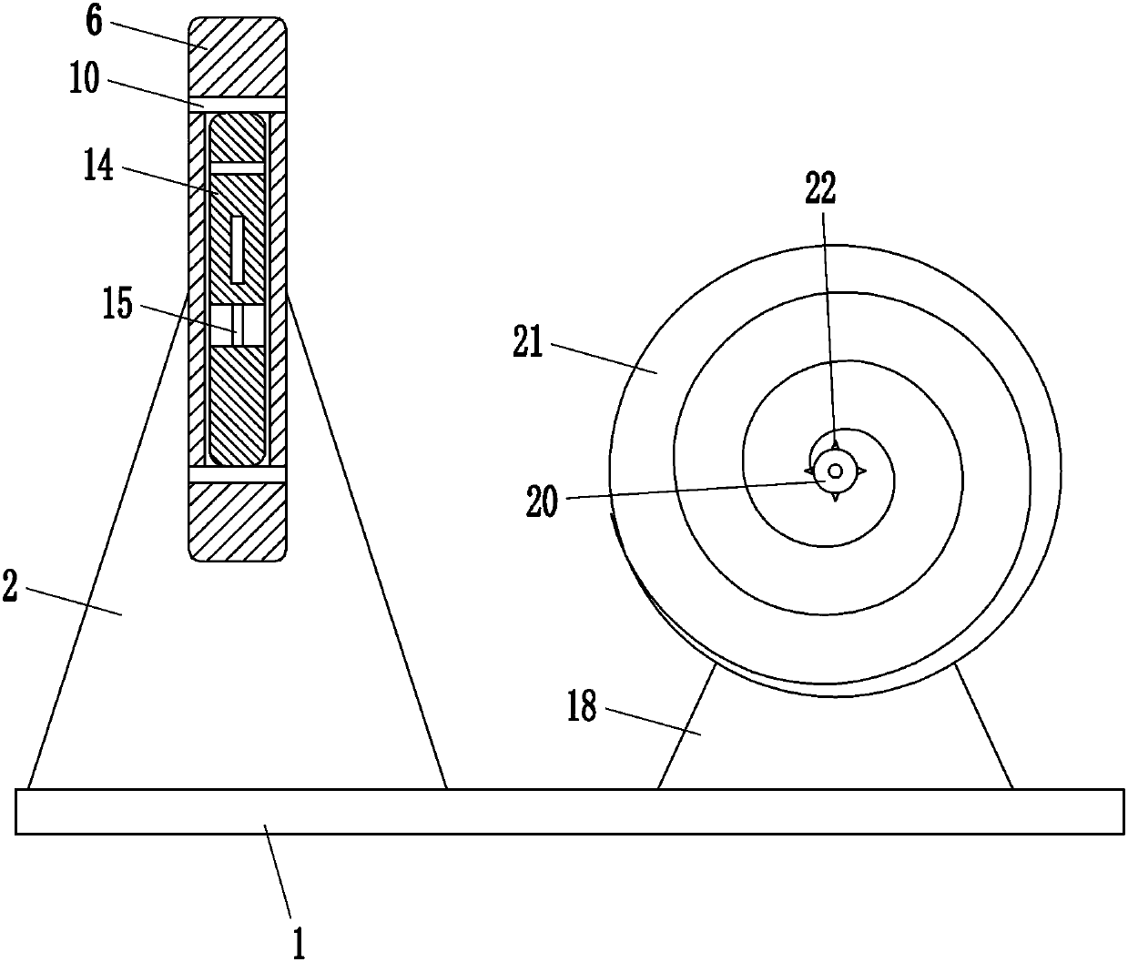
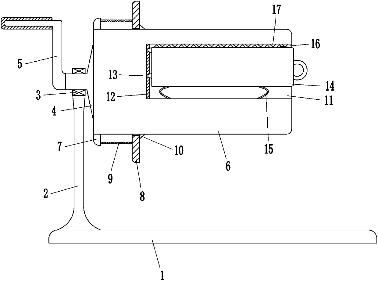
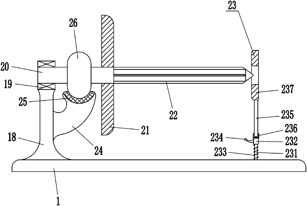
[0017] A plaster bandage folding machine such as Figure 1-3 As shown, it includes a base plate 1, a support plate 2, a first bearing seat 3, a rotating shaft 4, a rocker 5, a rotating plate 6, a connecting block 7, an annular push plate 8, an elastic rope 9, a push block 10, a slide rail 12, Slider 13, pressure plate 14, shrapnel 15, lower tooth block 16, upper tooth block 17, support plate 18, second bearing seat 19, rotating rod 20, circular plate 21 and convex strip 22, the top left front side of bottom plate 1 is fixed There is a support plate 2 for support, the first bearing seat 3 is bolted to the top of the support plate 2, a T-shaped rotating shaft 4 is installed in the first bearing seat 3, and a 7-shaped rocker 5 is fixedly connected to the rotating shaft 4, the left end and the right end of the rotating shaft 4 are connected with a rotary plate 6, two connecting blocks 7 are arranged on the upper and lower sides of the left part of the rotary plate 6, and the left ...

Embodiment 2

[0019] A plaster bandage folding machine such as Figure 1-3 As shown, it includes a base plate 1, a support plate 2, a first bearing seat 3, a rotating shaft 4, a rocker 5, a rotating plate 6, a connecting block 7, an annular push plate 8, an elastic rope 9, a push block 10, a slide rail 12, Slider 13, pressure plate 14, shrapnel 15, lower tooth block 16, upper tooth block 17, support plate 18, second bearing seat 19, rotating rod 20, circular plate 21 and convex strip 22, the top left front side of bottom plate 1 is fixed There is a support plate 2 for support, the first bearing seat 3 is bolted to the top of the support plate 2, a T-shaped rotating shaft 4 is installed in the first bearing seat 3, and a 7-shaped rocker 5 is fixedly connected to the rotating shaft 4, the left end and the right end of the rotating shaft 4 are connected with a rotary plate 6, two connecting blocks 7 are arranged on the upper and lower sides of the left part of the rotary plate 6, and the left ...

Embodiment 3

[0022] A plaster bandage folding machine such as Figure 1-3 As shown, it includes a base plate 1, a support plate 2, a first bearing seat 3, a rotating shaft 4, a rocker 5, a rotating plate 6, a connecting block 7, an annular push plate 8, an elastic rope 9, a push block 10, a slide rail 12, Slider 13, pressure plate 14, shrapnel 15, lower tooth block 16, upper tooth block 17, support plate 18, second bearing seat 19, rotating rod 20, circular plate 21 and convex strip 22, the top left front side of bottom plate 1 is fixed There is a support plate 2 for support, the first bearing seat 3 is bolted to the top of the support plate 2, a T-shaped rotating shaft 4 is installed in the first bearing seat 3, and a 7-shaped rocker 5 is fixedly connected to the rotating shaft 4, the left end and the right end of the rotating shaft 4 are connected with a rotary plate 6, two connecting blocks 7 are arranged on the upper and lower sides of the left part of the rotary plate 6, and the left pa...


PUM


Abstract

The invention relates to a folding machine, in particular to a plaster bandage folding machine. The invention aims at providing the plaster bandage folding machine which can save time and improve thefolding efficiency. According to the technical implementation scheme, the plaster bandage folding machine is characterized by comprising a bottom plate, a supporting plate, a first bearing pedestal, arotating shaft, a rocker rod, a rotating plate, a connecting block, an annular push plate, an elastic rope, a push block, sliding rails, a sliding block, a pressing plate, an elastic sheet and the like, wherein the supporting plate for supporting is fixedly connected with the front left side of the top of the bottom plate; the first bearing pedestal is bolted to the top of the supporting plate; the T-shaped rotating shaft is installed in the first bearing pedestal; the L-shaped rocker rod is fixedly connected with the left end of the rotating shaft; and the rotating plate is connected with the right end of the rotating shaft. According to the invention, the rotating plate can be driven to rotate clockwise by rotating the rocker rod clockwise so as to fold a plaster bandage, and medical workers do not need to cut the plaster bandage and then fold the plaster bandage manually, so that the time is saved and the folding efficiency is improved.

Description

technical field [0001] The invention relates to a folding machine, in particular to a plaster bandage folding machine. Background technique [0002] Plaster bandages are made of starched gauze bandages and plaster of paris powder. After soaking in water, they can be hardened and shaped in a short time. They have strong shaping ability and good stability. They are one of the commonly used items in orthopedics. First, in order to better use the plaster bandage, it is necessary to fold the plaster bandage. At present, the medical staff generally cuts the plaster bandage manually, and then folds the plaster bandage. In this way, it takes a lot of time and the folding efficiency is low. ; In order to improve folding efficiency and save time, other medical staff are needed to help fold, which is a waste of manpower. Contents of the invention [0003] In order to overcome the shortcomings of the medical staff who manually cut the plaster bandages and then fold the plaster bandag...

Claims


Application Information

Patent Timeline
Patent Type & Authority Applications(China)
IPC IPC(8): A61F15/00A61F15/02
CPCA61F15/007A61F15/02
Inventor 曾竞
Owner THE PEOPLES HOSPITAL SHAANXI PROV
Why Eureka
Try Eureka