Cutting tool bit for light guide plates

A technology for cutting cutter head and light guide plate, which is applied in metal processing and other directions, and can solve the problems of uneven cross-section of the light guide plate, inability to effectively delineate pits, and roughness.

Inactive Publication Date: 2017-09-26
东莞质研工业设计服务有限公司
View PDF0 Cites 1 Cited by
  • Summary
  • Abstract
  • Description
  • Claims
  • Application Information

AI Technical Summary

Problems solved by technology

[0003] However, because this method is extended from the traditional light guide plate, there are many kinds of light guide plate with its own development, such as the light guide plate with many bumps and pits on the surface, so it can be done with ordinary scratches. When scribing, the pit cannot be effectively scribbled, resulting in uneven cross-section or rough appearance when the light guide plate is opened.

Method used


Image

  • Cutting tool bit for light guide plates
  • Cutting tool bit for light guide plates
  • Cutting tool bit for light guide plates

Examples


Embodiment Construction

[0017] The present invention will be described in further detail below in conjunction with the accompanying drawings and specific embodiments, and the implementation scope of the present invention is not limited thereto.

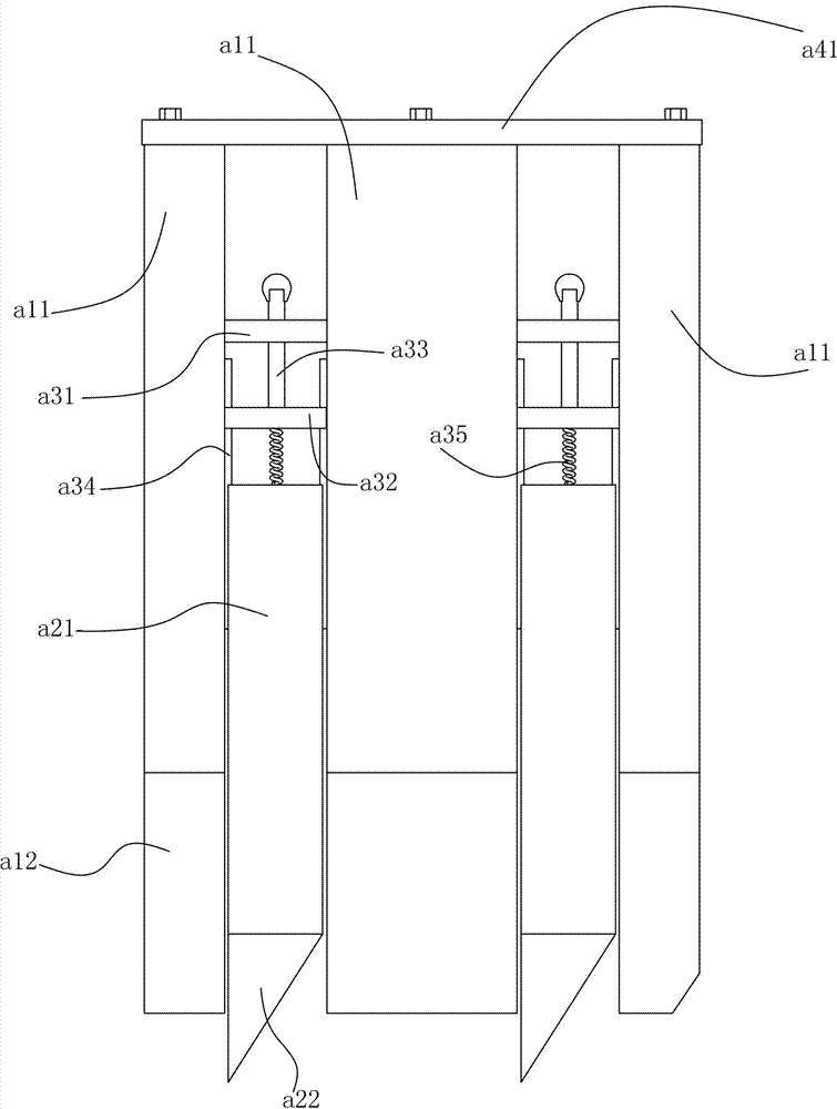
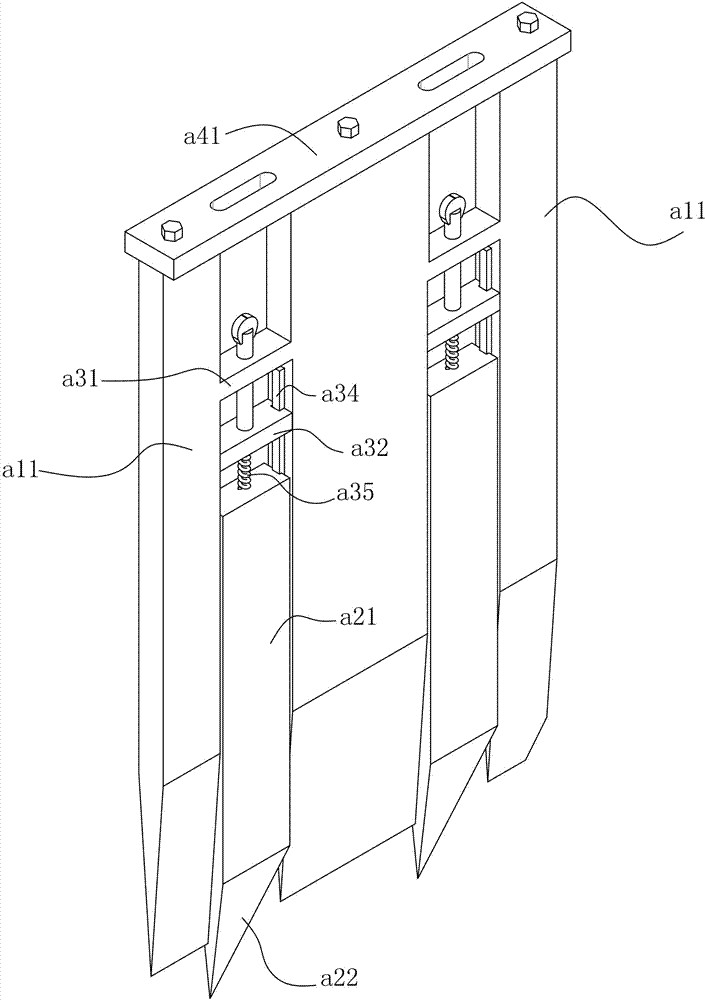
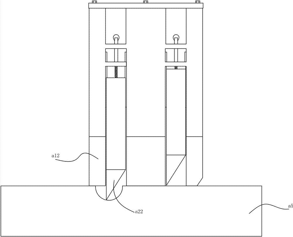
[0018] Such as Figure 1 to Figure 2 As shown, a light guide plate cutting head described in this embodiment includes three main cutting heads a11, and a wedge-shaped main blade a12 is provided at the bottom of each main cutting head a11;

[0019] A connecting rod a31 is provided between two adjacent main cutter heads a11, and a convex corrugation a34 is arranged on the opposite side between two adjacent main cutter heads a11, and a slide is provided between two adjacent main cutter heads a11. Block a32, the two sides of slide block a32 are provided with the first guide groove that cooperates with convex a34; Also include screw rod a33, the bottom of described screw rod a33 is connected with the top of slide block a32, screw rod a33 passes connecting rod a31...


PUM


Abstract

The invention discloses a cutting tool bit for light guide plates. The cutting tool bit comprises three main tool bits; a wedge-shaped main blade is arranged at the bottom of each main tool bit; a connecting rod is arranged between every two adjacent main tool bits; and ribs are arranged on the opposite side surfaces of every two adjacent main tool bits. The cutting tool bit further comprises sliding blocks arranged between every two adjacent main tool bits; and first guide grooves matched with the ribs are formed in two sides of the sliding blocks. The cutting tool bit further comprises screws; the bottoms of the screws are connected with the tops of the sliding blocks; the screws penetrate through the connecting rods; and the tops of the screws are in threaded connection with adjusting nuts. With two groups of tool bits, one group is retractable, cutting seams in the surfaces of the light guide plates can be effectively cut in place, and the conditions that the edges of the light guide plates are coarse and irregular when the light guide plates are split due to positions which are not cut can be avoided.

Description

technical field [0001] The invention relates to a cutter head for cutting a light guide plate. Background technique [0002] Since the light guide plate is similar to an acrylic plate, there are many ways to cut the light guide plate, including laser or direct cutting, but the current relatively low-cost or relatively simple cutting method is to draw a line on the light guide plate, and then press on both sides. Disconnect the light guide plate like scratching glass. [0003] However, because this method is extended from the traditional light guide plate, there are many kinds of light guide plate with its own development, such as the light guide plate with many bumps and pits on the surface, so it can be done with ordinary scratches. When scribing, the pits cannot be effectively scribbled, resulting in uneven cross-sections or roughness when the light guide plate is opened. Contents of the invention [0004] The object of the present invention is to overcome the above-me...

Claims


Application Information

Patent Timeline
Patent Type & Authority Applications(China)
IPC IPC(8): B26D1/04B26D7/26
CPCB26D1/04B26D7/2614B26D7/2628B26D2001/0033
Inventor 谢广鹏
Owner 东莞质研工业设计服务有限公司
Why Eureka
Try Eureka