Mining crowbar with direction guide mechanism for mine construction

A technology of guiding mechanism and crowbar, which is applied in the direction of crowbar, lifting device, etc., which can solve the problems of manual prying of rocks, inconvenient fixing of crowbar, inconvenient force application of crowbar, etc.

Inactive Publication Date: 2021-04-20
尤保华
View PDF9 Cites 0 Cited by
  • Summary
  • Abstract
  • Description
  • Claims
  • Application Information

AI Technical Summary

Problems solved by technology

[0003] During the mine construction process, the rocks on the mine need to be mined, and a practical crowbar is needed to pry the large rocks. When the existing crowbars pry the rocks, it is difficult to insert the pry head into the gap of the rocks. It is inconvenient to fix the pry head, and when prying, it is very laborious to manually pry the rock, and it is inconvenient to lift the crowbar upward to apply force

Method used


Image

  • Mining crowbar with direction guide mechanism for mine construction
  • Mining crowbar with direction guide mechanism for mine construction
  • Mining crowbar with direction guide mechanism for mine construction

Examples


Embodiment 1

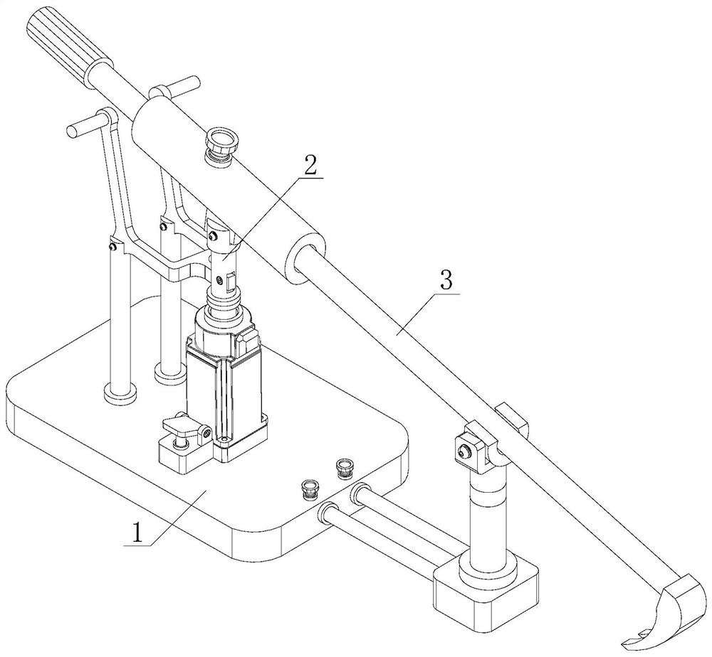
[0032] see figure 1 , a mining crowbar with a direction guide mechanism for mine construction, including a support guide unit 1, a force application unit 2 and a crowbar unit 3, the crowbar unit 3 is movably installed on the force application unit 2, and the force application unit 2 is fixed Mounted on the support guide unit 1.

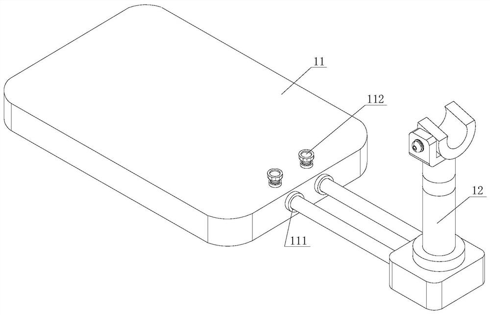
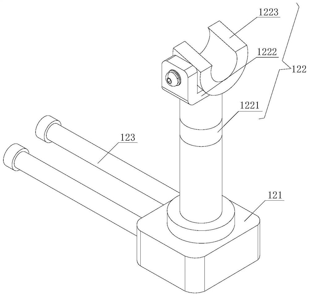
[0033] see Figure 2-3 , the support guide unit 1 is provided with a support base plate 11 and a guide piece 12, and one end of the support base plate 11 is movably installed with the guide piece 12 to form the support guide unit 1 as a whole, and the force applying unit 2 is fixedly installed on the upper end surface of the support base plate 11 to support the base plate 11 is provided with a connecting hole 111 and a first fixing bolt 112, the connecting hole 111 is opened at one end of the supporting base plate 11, the first fixing bolt 112 is threadedly installed on one end of the upper end surface of the supporting base plate 11, and extends int...

Embodiment 2

[0038] see figure 1 , a mining crowbar with a direction guide mechanism for mine construction, including a support guide unit 1, a force application unit 2 and a crowbar unit 3, the crowbar unit 3 is movably installed on the force application unit 2, and the force application unit 2 is fixed Mounted on the support guide unit 1.

[0039] see Figure 2-3 , the support guide unit 1 is provided with a support base plate 11 and a guide piece 12, and one end of the support base plate 11 is movably installed with the guide piece 12 to form the support guide unit 1 as a whole, and the force applying unit 2 is fixedly installed on the upper end surface of the support base plate 11 to support the base plate 11 is provided with a connecting hole 111 and a first fixing bolt 112, the connecting hole 111 is opened at one end of the supporting base plate 11, the first fixing bolt 112 is threadedly installed on one end of the upper end surface of the supporting base plate 11, and extends int...


PUM


Abstract

The invention discloses a mining crowbar with a direction guide mechanism for mine construction. The mining crowbar comprises a supporting guide unit, a force application unit and a crowbar unit, wherein the crowbar unit is movably installed on the force application unit, the force application unit is fixedly installed on the supporting guide unit, a U-shaped groove block is fixed to the upper end of a supporting column through a connecting lug block, one end of a rod body of the crowbar unit is movably arranged in a groove of the U-shaped groove block, when the crowbar unit is pulled, the rod body can be positioned through the U-shaped groove block, so that the moving direction of the rod body is guided, the rod body of the crowbar unit is movably inserted into a pipe body of a connecting sleeve pipe piece, the pipe body limits the movement of the rod body, when the crowbar unit is moved, the pipe body can also play a role in direction guiding, the crowbar unit can be positioned when moving, a crowbar head cannot deviate from a gap of rock, and the crowbar head can be conveniently inserted into the gap of the rock.

Description

technical field [0001] The invention relates to the technical field of mine construction tools, in particular to a mining crowbar with a direction guiding mechanism for mine construction. Background technique [0002] Mine refers to an independent production and operation unit that extracts ore with a certain mining boundary. Mine mainly includes one or more mining workshops (or pitheads, mine shafts, open pits, etc.) and some auxiliary workshops, and most mines also include ore dressing plants (coal washing plants). [0003] During the mine construction process, the rocks on the mine need to be mined, and a practical crowbar is needed to pry the large rocks. When the existing crowbars pry the rocks, it is difficult to insert the pry head into the gap of the rocks. It is inconvenient to fix the prying head, and when prying, it is very laborious to manually pry the rock, and it is inconvenient to apply force by lifting the crowbar upwards. [0004] In view of the above prob...

Claims


Application Information

Patent Timeline
Patent Type & Authority Applications(China)
IPC IPC(8): B66F15/00
Inventor 尤保华
Owner 尤保华
Why Eureka
Try Eureka