

Cross-shaped pipeline robot
A pipeline robot, cross-shaped technology, applied in the direction of pipe components, mechanical equipment, pipes/pipe joints/pipe fittings, etc.
- Summary
- Abstract
- Description
- Claims
- Application Information
AI Technical Summary
Problems solved by technology
Method used
Image

Examples
Embodiment Construction
[0034] The following will clearly and completely describe the technical solutions in the embodiments of the present invention in conjunction with the accompanying drawings in the embodiments of the present invention; obviously, the described embodiments are only part of the embodiments of the present invention, not all embodiments, based on The embodiments of the present invention and all other embodiments obtained by persons of ordinary skill in the art without making creative efforts belong to the protection scope of the present invention.
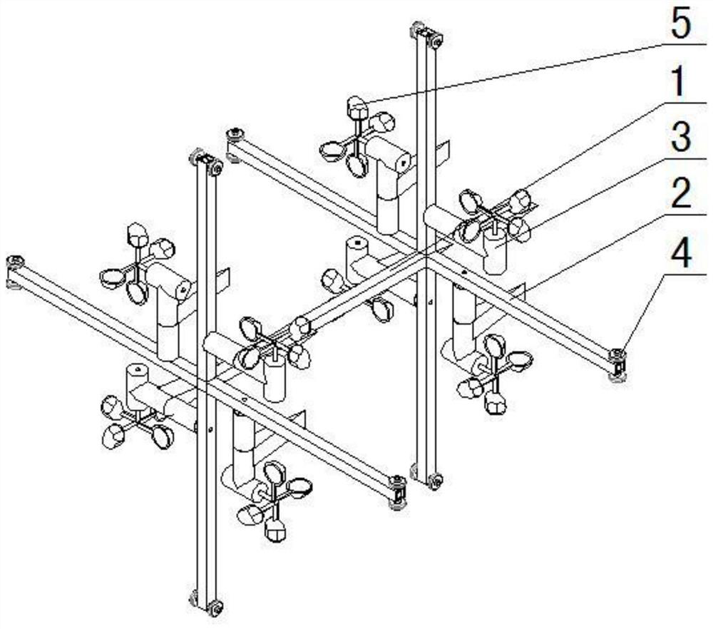
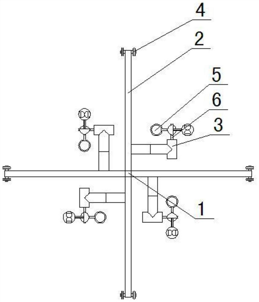
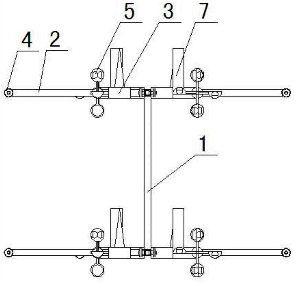
[0035] The cross-shaped pipeline robot includes two symmetrical cross-shaped supports, and the cross-shaped supports are connected by a connecting rod 1,
[0036] The cross-shaped support includes four supports 2 forming a cross, and each support end is equipped with a damping wheel 4,
[0037] A drive mechanism is installed vertically on each bracket,
[0038] The driving mechanism is installed vertically on the four brackets, forming ...
PUM
 Abstract
Description
Claims
Application Information