Supercharge Your Innovation With Domain-Expert AI Agents!

Novel high-gain Cuk DC-DC converter

A converter and high-gain technology, applied in the conversion equipment of the Cuk converter, the conversion device of the output power, the conversion of DC power input to DC power output, etc., can solve the problems of many switching components and large losses, and achieve The effect of low voltage stress and high input and output gain

Active Publication Date: 2021-04-27
CHINA THREE GORGES UNIV
View PDF3 Cites 0 Cited by
  • Summary
  • Abstract
  • Description
  • Claims
  • Application Information

AI Technical Summary

Problems solved by technology

[0003] In order to solve the problem that the existing isolated high-gain DC-DC converter has many switching components and large losses, the present invention proposes a new type of high-gain Cuk DC-DC converter based on the basic Cuk circuit

Method used


Image

  • Novel high-gain Cuk DC-DC converter
  • Novel high-gain Cuk DC-DC converter
  • Novel high-gain Cuk DC-DC converter

Examples


Embodiment Construction

[0033] The present invention will be described in further detail below in conjunction with the accompanying drawings.

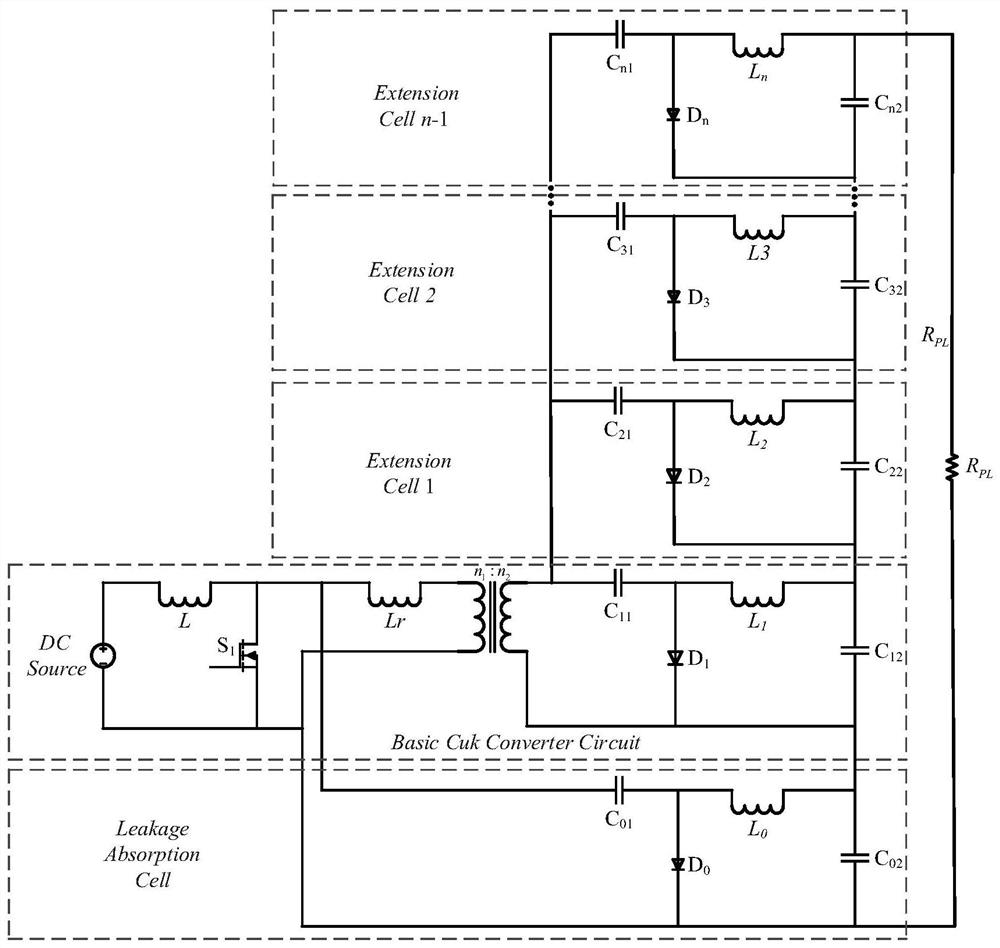
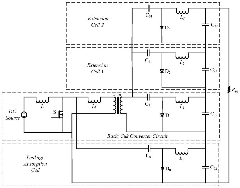
[0034] like figure 2 Shown is the circuit topology diagram when the number of gain expansion units of the present invention is n=3:

[0035] A new type of high-gain Cuk DC-DC converter, the converter includes a DC input source, a load, a basic Cuk converter, 2 gain extension units. in:

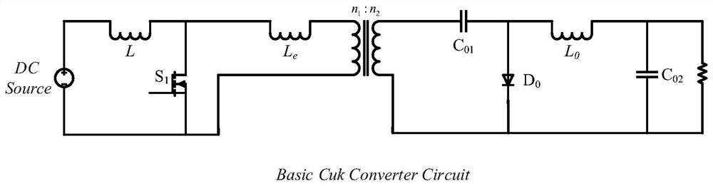
[0036] The basic Cuk converter consists of a primary and secondary n 1 :n 2 Transformer, three inductors L, L r , L 1 , two capacitors C 11 、C 12 , a power switch S 1 , a diode D 1; The connection form is as follows: one end of the inductor L is connected to the positive pole of the DC input source, and the other end of the inductor L is respectively connected to the power switch S 1 the drain as well as the inductance L r at one end, the inductance L r The other end of the transformer is connected to the upper end of the primary side, and the power switch S 1 T...


PUM


Abstract

The invention discloses a novel high-gain Cuk DC-DC converter. The converter comprises a direct-current input source, a basic Cuk converter and n-1 gain expansion units, wherein each gain expansion unit is composed of an inductor, two capacitors and a diode, and the input and output gain of the converter and the voltage stress of a switching device can be adjusted by adjusting the number of the gain expansion units. The converter has advantages of being simple in control and drive circuit, wide in input and output voltage adjusting range, low in switching device voltage stress and the like, and is suitable for application occasions with large input voltage and output voltage change ranges.

Description

technical field [0001] The invention relates to a DC-DC converter, in particular to a novel high-gain Cuk DC-DC converter. Background technique [0002] In applications where the input and output voltages vary greatly, the input voltage may be higher than the output voltage, or lower than the output voltage. At this time, the common non-isolated buck-boost DC-DC converters are Flyback, Cuk, Isolated Sepic and Isolated Zeta circuits. Theoretically, by adjusting the duty cycle D, the input and output gains of these converters can vary from zero to infinity, but due to the influence of components and circuit parasitic parameters, the boosting capability of these converters is greatly limited. At present, most of the schemes for increasing the input and output gain of DC-DC converters are based on isolated Boost circuits cascaded with DC transformers. Therefore, these circuits have many switching components and large losses. Therefore, it is of great significance to realize a ...

Claims


Application Information

Patent Timeline
IPC IPC(8): H02M3/00H02M3/335
CPCH02M3/005H02M3/33523
Inventor 邾玢鑫戴俊平张耀杨楠马辉
Owner CHINA THREE GORGES UNIV
Features
  • R&D
  • Intellectual Property
  • Life Sciences
  • Materials
  • Tech Scout
  • Unparalleled Data Quality
  • Higher Quality Content
  • 60% Fewer Hallucinations
Learn More