Control circuit of medical operation waste liquid collection device
A waste liquid collection and device control technology, applied in the field of medical devices, can solve the problems of infecting others, waste liquid overflowing the container, low work efficiency, etc., and achieve the effect of saving electric energy
- Summary
- Abstract
- Description
- Claims
- Application Information
AI Technical Summary
Problems solved by technology
Method used
Image
Examples
Embodiment 1
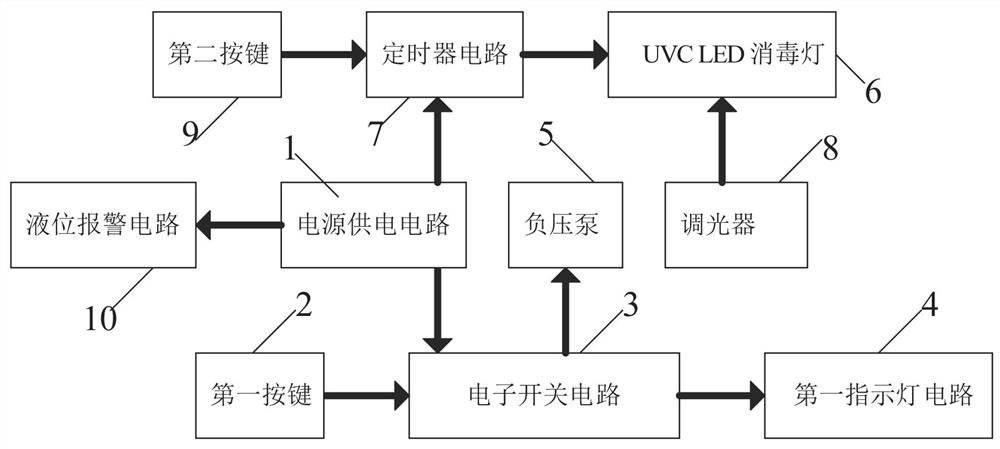
[0020] A control circuit of a medical operation waste liquid collection device, such as figure 1 As shown, it includes a power supply circuit 1, a first key 2, an electronic switch circuit 3, a first indicator light circuit 4 and a negative pressure pump 5, the first key 2 is connected to the input end of the electronic switch circuit 3, and the electronic The output end of the switch circuit 3 is connected to the input end of the first indicator light circuit 4, the output end of the electronic switch circuit 3 is connected to the input end of the negative pressure pump 5, and the power supply circuit 1 is the first button 2, the electronic switch circuit 3, The first indicator light circuit 4 and the negative pressure pump 5 supply power.
[0021] When the medical personnel need to collect the waste liquid produced by the operation, first press the first button 2, the electronic switch circuit 3 starts to work, the electronic switch circuit 3 controls the first indicator lig...
Embodiment 2
[0023] On the basis of Example 1, such as figure 1 As shown, also include UVC LED disinfection lamp 6, timer circuit 7, dimmer 8 and second key 9, described second key 9 is connected with timer circuit 7 input terminals, and described timer circuit 7 output terminals Connect with the UVC LED disinfection lamp 6 input terminals, the dimmer 8 output terminals are connected with the UVC LED disinfection lamp 6 input terminals, and the power supply circuit 1 is a UVC LED disinfection lamp 6, a timer circuit 7, and a dimmer 8 and the second button 9 to supply power.
[0024] When the electronic switch circuit 3 starts to work, press the second button 9 at the same time, the timer circuit 7 starts to work, the timer circuit 7 drives the UVC LED disinfection lamp 6 to work, and the UVC LED disinfection lamp 6 disinfects the collected waste liquid. The personnel can adjust the power of the UVC LED disinfection lamp 6 through the dimmer 8. After the waste liquid collection is complete...
Embodiment 3
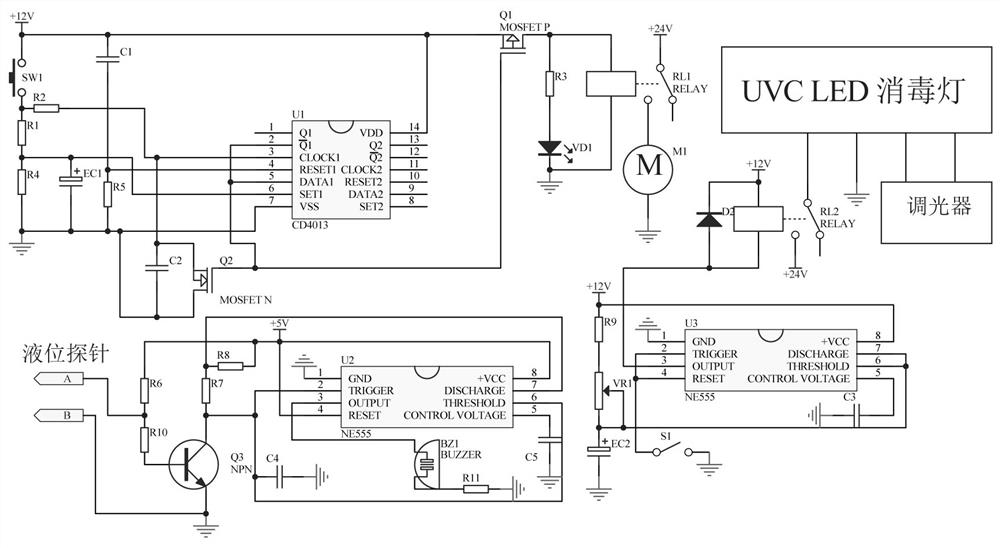
[0028] A control circuit of a medical operation waste liquid collection device, such as figure 2 As shown, the electronic switch circuit 3 includes a double D-type flip-flop CD4013-U1, a tact switch SW1, capacitors C1~C2, electrolytic capacitors EC1, resistors R1~Q2, resistors R4~R5, and an N-channel field effect transistor Q2 and P-channel field effect transistor Q1, the 2 pins of the double D flip-flop CD4013-U1 are connected to its 5 pins, the 2 pins of the double D flip-flop CD4013-U1 are connected in series with the N-channel field effect transistor Q2, the N The source of the N-channel field effect transistor Q2 and its drain are connected in parallel with a capacitor C2, the common terminal after the drain of the N-channel field effect transistor Q2 is connected in parallel with the capacitor C2 is grounded, and the source of the N-channel field effect transistor Q2 is connected in parallel with the capacitor C2 The common terminal of the double D-type flip-flop CD4013...
PUM
 Abstract
Description
Claims
Application Information
 - R&D
- Intellectual Property
- Life Sciences
- Materials
- Tech Scout
- Unparalleled Data Quality
- Higher Quality Content
- 60% Fewer Hallucinations
Browse by: Latest US Patents, China's latest patents, Technical Efficacy Thesaurus, Application Domain, Technology Topic, Popular Technical Reports.
© 2025 PatSnap. All rights reserved.Legal|Privacy policy|Modern Slavery Act Transparency Statement|Sitemap|About US| Contact US: help@patsnap.com


