
Dye stirring device for rotary screen printing machine

A technology of rotary screen printing and stirring device, which is applied in the directions of mixer, transportation and packaging, dissolving, etc., can solve the problems of poor stirring effect, single stirring form, and slow stirring of dyestuffs evenly.

Inactive Publication Date: 2021-04-30
FUJIAN JINJIANG JILONG MACHINE IND
View PDF6 Cites 0 Cited by
  • Summary
  • Abstract
  • Description
  • Claims
  • Application Information

AI Technical Summary

Problems solved by technology

[0003] The mixing of dyes is usually carried out with a dye mixing device. Most of the existing dye mixing devices are composed of a separate mixing tank and a stirring motor. Multiple dyes are directly poured into the mixing tank, and then the stirring shaft is driven by the stirring motor to stir. There are many dyes that need to be mixed and stirred at the same time. Many kinds of dyes are poured in and stirred at the same time. In addition, most of the fuel is stirred horizontally when stirring, and it cannot be rolled up and down. In addition, the stirring form is too single, so that the stirring device is slow to stir the dye evenly, the stirring effect is poor, and the work efficiency is reduced

Method used


Image

  • Dye stirring device for rotary screen printing machine
  • Dye stirring device for rotary screen printing machine

Examples


Embodiment Construction

[0015] The present invention will be described in further detail below in conjunction with the accompanying drawings.

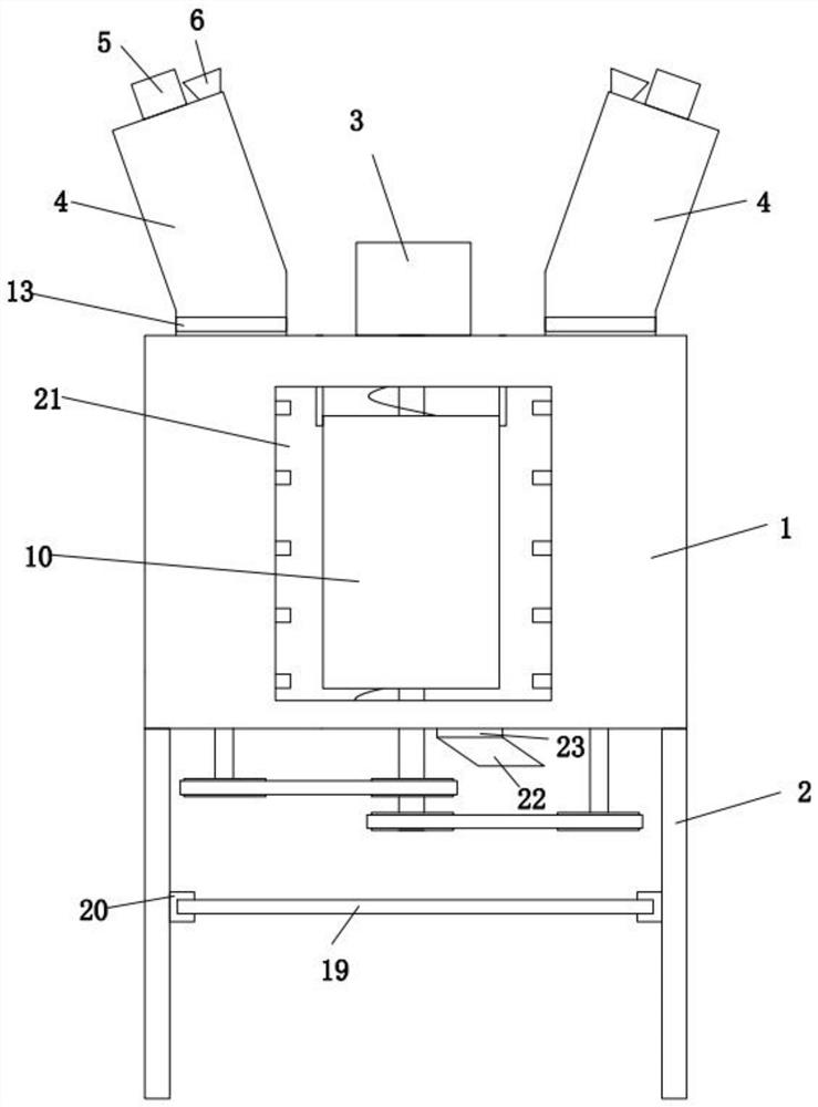
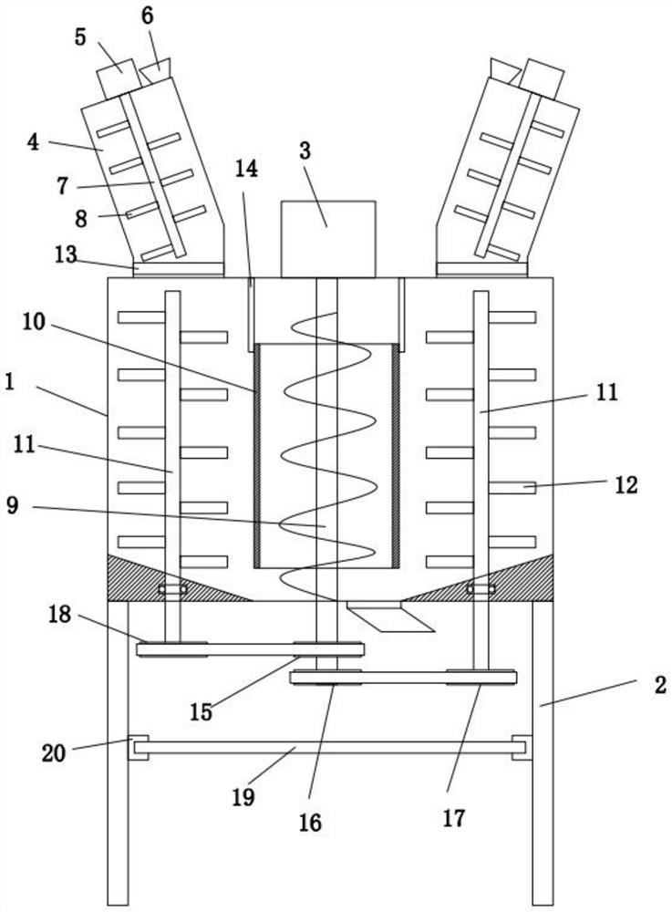
[0016] A dye stirring device for a rotary screen printing machine, comprising a barrel body 1, the lower end of the barrel body 1 is provided with a leg 2, the upper end of the barrel body 1 is provided with a motor one 3 and a stirring machine located on both sides of the motor one 3 barrel 4, the upper end of the mixing barrel 4 is provided with a motor two 5 and a feed port 6, the stirring barrel 4 is provided with a stirring shaft one 7 connected with the motor two 5, and the stirring shaft one 7 is provided with a stirring blade - 8, a solenoid valve 13 is provided at the connection between the lower end of the mixing tank 4 and the barrel body 1, the barrel body 1 is provided with an outer cover 10 and a screw conveying shaft 9 connected to the motor one 3 and located in the outer cover 10, Both sides of the outer cover 10 in the barrel body 1 are provi...


PUM


Abstract

The present invention discloses a dye stirring device for a rotary screen printing machine. The dye stirring device comprises a barrel body, supporting legs are arranged at the lower end of the barrel body, a first motor and stirring barrels located on the two sides of the first motor are arranged at the upper end of the barrel body, a second motor and a feeding port are arranged at the upper ends of the stirring barrels, and a first stirring shaft connected with the second motor is arranged in each stirring barrel; a first stirring blade is arranged on the first stirring shaft, a first electromagnetic valve is arranged at the communication position of the lower end of the stirring barrel and the barrel body, an outer cover and a spiral conveying shaft connected with the first motor and located in the outer cover are arranged in the barrel body, and second stirring shafts driven by the first motor are arranged on the two sides of the outer cover in the barrel body; and a second stirring blade is arranged on the second stirring shaft, and a discharging port and a second electromagnetic valve located on the discharging port are arranged at the lower end of the barrel body. Compared with the prior art, the stirring device has the advantages that the stirring forms are diversified, so that the stirring is uniform, the speed is high, and the stirring efficiency and the working efficiency are improved.

Description

technical field [0001] The invention relates to the technical field of dye stirring devices, in particular to a dye stirring device for a rotary screen printing machine. Background technique [0002] The rotary screen printing machine is mainly a device for printing on the surface of the fabric. We see many types and styles of fabrics in our daily life, and they are usually printed with colorful patterns. The origin of these patterns is mostly the use of mixed dyes. , and then printed out by a rotary screen printing machine, so the quality of printing is directly related to the quality of dye mixing. [0003] The mixing of dyes is usually carried out with a dye mixing device. Most of the existing dye mixing devices are composed of a separate mixing tank and a stirring motor. Multiple dyes are directly poured into the mixing tank, and then the stirring shaft is driven by the stirring motor to stir. There are many dyes that need to be mixed and stirred at the same time. Many ...

Claims


Application Information

Patent Timeline
Patent Type & Authority Applications(China)
IPC IPC(8): B01F13/10
CPCB01F33/821B01F2101/30
Inventor 陈进展陈凡陈英伦
Owner FUJIAN JINJIANG JILONG MACHINE IND
Learn More