Small reinforcing steel bar looping device for construction site

A construction site, small-scale technology, which is applied in the field of small steel bar ring forming devices for construction sites, can solve the problems of time-consuming, work efficiency, and easily injured labor force, and achieve the effect of reducing scratches and saving manpower

Active Publication Date: 2021-04-30
无锡双龙艺术装潢有限公司
View PDF6 Cites 0 Cited by
  • Summary
  • Abstract
  • Description
  • Claims
  • Application Information

AI Technical Summary

Problems solved by technology

[0004] In order to overcome the shortcomings of easy injury, high labor intensity, time-consuming and low work efficiency, the technical problem to be solved is: to provide a small-scale steel ring forming device for construction sites that can automatically make ring steel bars and has high work efficiency

Method used


Image

  • Small reinforcing steel bar looping device for construction site
  • Small reinforcing steel bar looping device for construction site
  • Small reinforcing steel bar looping device for construction site

Examples


Embodiment 1

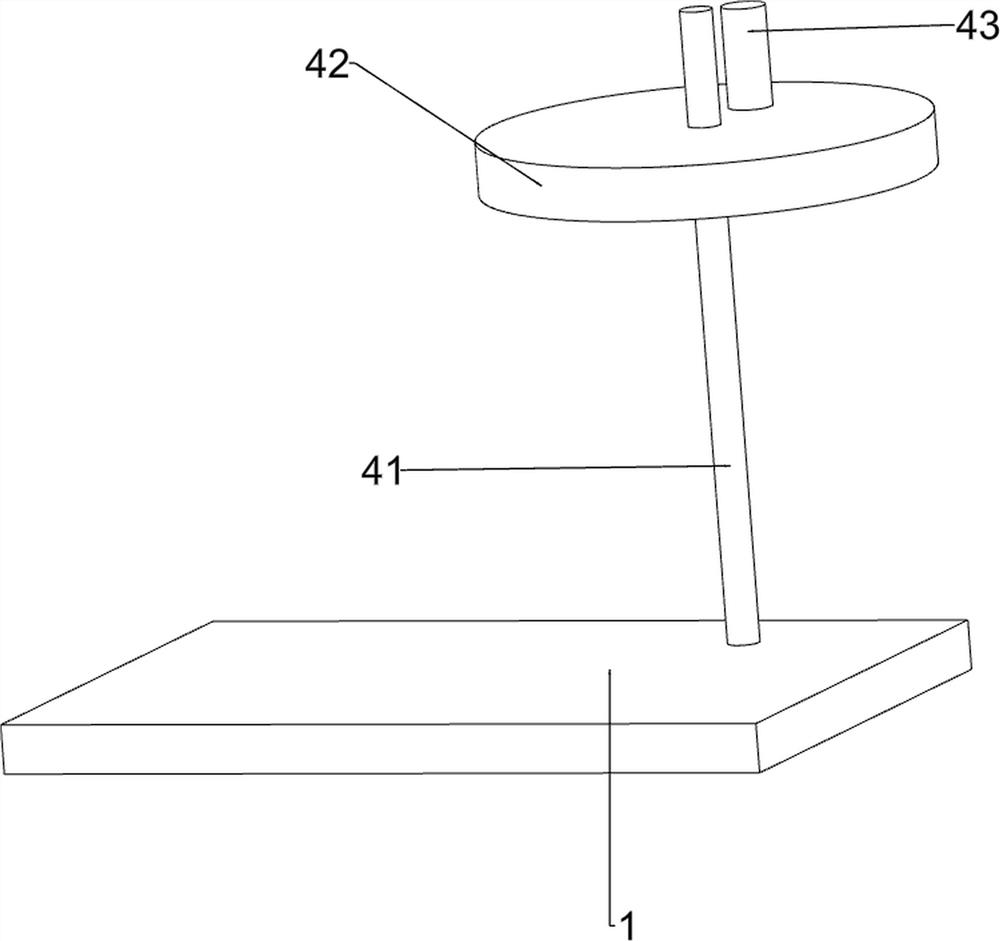
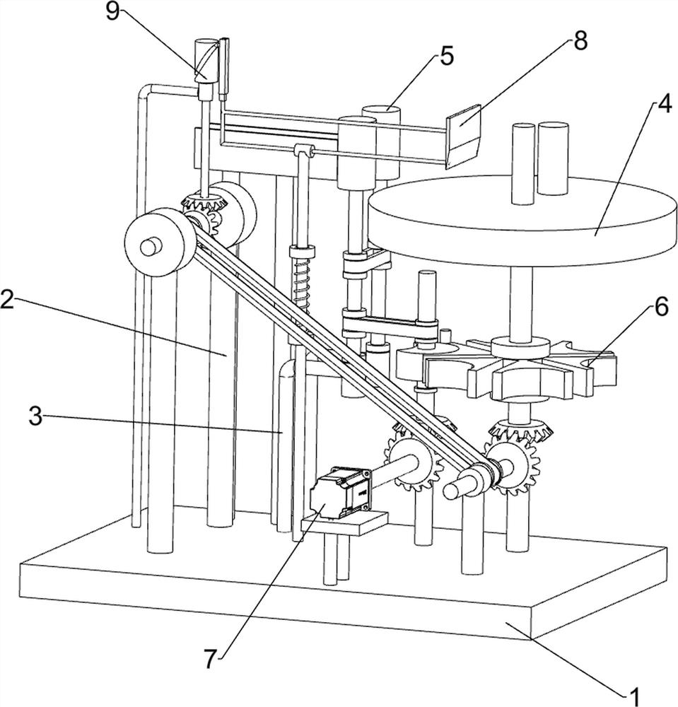
[0028] A small steel bar ring forming device for a construction site, such as Figure 1-Figure 3 As shown, it includes a first fixed plate 1, a first support rod 2, a first L-shaped rod 3, a discharging mechanism 4 and a feeding mechanism 5, and the left, right and left sides of the first fixed plate 1 are provided with first supports. Rod 2, the first L-shaped rod 3 is provided on the front and rear sides of the upper left part of the first fixed plate 1, and the rear side of the upper right part of the first fixed plate 1 is provided with a discharge mechanism 4, and the first support rod 2 and the first L A feeding mechanism 5 is provided between the shaped rods 3 .

[0029] When people need to make the reinforcing bar into a ring, people manually place the reinforcing bar in the feeding mechanism 5, and manually push the reinforcing bar so that the reinforcing bar is in the discharging mechanism 4, and people manually rotate the discharging mechanism 4, so that the reinfor...

Embodiment 2

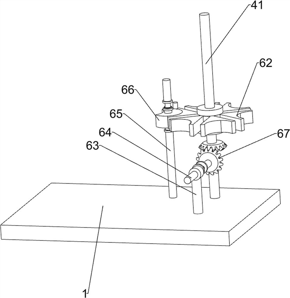
[0035] On the basis of Example 1, such as figure 1 , Figure 4-Figure 7 As shown, it also includes a turning mechanism 6, and the turning mechanism 6 includes an intermittent gear 62, a second support rod 63, a fifth rod 64, a sixth rod 65, a toggle block 66 and a bevel gear set 67, and the first rod Part 41 middle part is provided with intermittent gear 62, and first fixed plate 1 upper right middle part is provided with second support bar 63, and the second support bar 63 is provided with the fifth bar member 64 in rotation, and first fixed plate 1 upper middle part rear There is a sixth rod 65 on the side, and a toggle block 66 is arranged on the sixth rod 65. The toggle block 66 meshes with the intermittent gear 62, and a bevel gear set is arranged between the fifth rod 64 and the first rod 41. 67.

[0036]In order to make it easier for people to loop the steel bars, people manually turn the sixth rod 65, so that the sixth rod 65 drives the toggle block 66 to rotate, and...


PUM


Abstract

The invention relates to a small reinforcing steel bar looping device, in particular to a small reinforcing steel bar looping device for a construction site. The invention provides the small reinforcing steel bar looping device for the construction site which is capable of automatically manufacturing annular reinforcing steel bars and high in working efficiency. The small reinforcing steel bar looping device for the construction site comprises a first fixing plate, first supporting rods, first L-shaped rods, a discharging mechanism, a feeding mechanism and the like, the first supporting rods are arranged on the left side and the right side of the left portion of the first fixing plate, the first L-shaped rods are arranged on the front side and the rear side of the left portion of the first fixing plate, the discharging mechanism is arranged on the rear side of the right portion of the first fixing plate, and the feeding mechanism is arranged between the first supporting rods and the first L-shaped rods. According to the small reinforcing steel bar looping device, through mutual cooperation of the discharging mechanism and the feeding mechanism, people place the reinforcing steel bars on a feeding part, then people push the reinforcing steel bars to a discharging disc, then the discharging disc is rotated to form the reinforcing steel bars into an annular shape.

Description

technical field [0001] The invention relates to a small steel bar loop forming device, in particular to a small steel bar loop forming device for a construction site. Background technique [0002] When people need to loop the steel bars, the workers need to manually place the steel bars on the rotating table, and then slowly make the steel bars into a ring. The process of making the rings requires a lot of strength, and the amount of work on the general construction site is large. , the demand for ring-shaped steel bars is large, and the requirements for workers are high, so that the steel bars produced cannot keep up with the demand, and the labor force for workers is relatively large. In addition, the steel bars need to be manually rotated during the loop forming process, which is easy to be cut. And work efficiency is not high. [0003] To sum up, the looping process of steel bars is easy to be injured and labor-intensive, time-consuming and low-efficiency. To design a s...

Claims


Application Information

Patent Timeline
Patent Type & Authority Applications(China)
IPC IPC(8): B21F1/00B21F11/00B21F23/00B21C47/18
CPCB21F1/006B21F11/00B21F23/00B21C47/18Y02P70/10
Inventor 胡萍
Owner 无锡双龙艺术装潢有限公司
Why Eureka
Try Eureka