Steel bar two-end bending device for construction site

A steel bar and two-end technology, which is applied in the field of two-end bending devices for steel bars on construction sites, can solve the problems of affecting the use of steel bars and large errors in bending positions

Active Publication Date: 2021-04-30
新疆隆泉建设集团有限公司
View PDF7 Cites 1 Cited by
  • Summary
  • Abstract
  • Description
  • Claims
  • Application Information

AI Technical Summary

Problems solved by technology

[0005] In order to overcome the danger of manually using tools to bend steel bars, and the degree of bending steel bars is different with different strengths of people, it is easy to cause large errors in the bending position and affect the use of steel bars. Technical problems : Provide a device capable of double-end bending, automatic bending, and error-reduced steel bar double-bending on site

Method used


Image

  • Steel bar two-end bending device for construction site
  • Steel bar two-end bending device for construction site
  • Steel bar two-end bending device for construction site

Examples


Embodiment 1

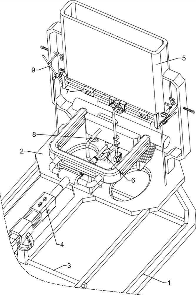
[0074] A device for bending steel bars at both ends on a construction site, such as figure 1 As shown, it includes a first fixed frame 1, a second fixed frame 2, a third fixed frame 3, a bending mechanism 4 and a discharge mechanism 5, and a third fixed frame is arranged between the front and rear sides of the upper right part of the first fixed frame 1. Frame 3, the second fixed frame 2 is provided between the third fixed frame 3 and the upper left side of the first fixed frame 1, the second fixed frame 2 is provided with a bending mechanism 4, and the left top of the second fixed frame 2 is provided with an outlet Material mechanism 5.

[0075] When people need to bend the two ends of the steel bar, they can use this device for bending the two ends of the steel bar on the construction site. First, people need to put the steel bar in the discharge mechanism 5. When it is necessary to bend the steel bar, people can pull the discharge Mechanism 5 moves upwards, so that the ste...

Embodiment 2

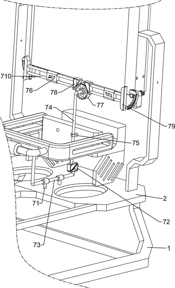
[0077] On the basis of Example 1, such as Figure 3-Figure 5 As shown, the bending mechanism 4 includes a cylinder 41, a bending rod 42, the fourth fixed mount 43, a U-shaped material rack 44 and a steel bar 45, and the upper side of the second fixed mount 2 right is equipped with a cylinder 41, and the expansion and contraction of the cylinder 41 The bar is provided with a bending bar 42, and the second fixed mount 2 is provided with a fourth fixed mount 43 on the front and rear sides of the left top, and a U-shaped material rack 44 is arranged between the two fourth fixed mounts 43, and the U-shaped material rack A reinforcing bar 45 is placed in the middle of 44 interiors.

[0078] People put the steel bar 45 on the U-shaped material rack 44, and then start the cylinder 41. When the telescopic rod of the cylinder 41 moves to the left, the telescopic rod of the cylinder 41 drives the bending rod 42 to move to the left, so that the bending rod 42 is opposite to the steel bar....

Embodiment 3

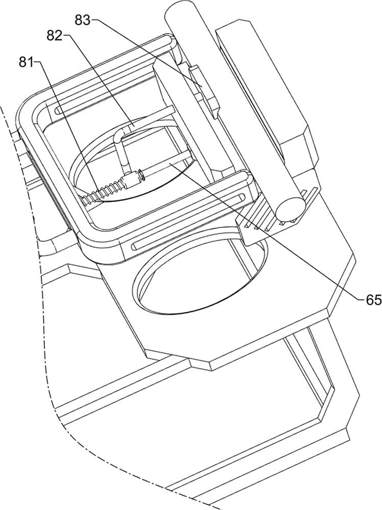
[0082] On the basis of Example 2, such as figure 2 , Figure 6-Figure 9 As shown, the ejection mechanism 6 is also included, and the ejection mechanism 6 includes a sixth fixed mount 61, a positioning block 62, a lever 63, an ejection block 64 and a first driving rod 65, and the middle of the second fixed mount 2 is front and rear. Both sides are provided with the sixth fixed mount 61, the second fixed mount 2 is provided with a positioning block 62 at the middle top on the left side, and a lever 63 is arranged in rotation between the tops of the two sixth fixed mounts 61, and a lever 63 is arranged at the top of the left side of the lever 63. Eject block 64, and the middle bottom of bending bar 42 right sides is provided with the first driving rod 65, and the first driving rod 65 cooperates with lever 63.

[0083] When the bending rod 42 moved to the right, the bending rod 42 drove the first driving rod 65 to move to the right, and when the first driving rod 65 was in conta...


PUM


Abstract

The invention relates to a bending device, in particular to a steel bar two-end bending device for a construction site. The steel bar two-end bending device for the construction site can bend the two ends of a reinforcing steel bar automatically and reduce errors. The steel bar two-end bending device for the construction site comprises: a first fixing frame and a third fixing frame, wherein the third fixing frame is arranged between the two sides of the upper portion of the first fixing frame. a second fixing frame, wherein the second fixing frame is arranged between the upper side of the third fixing frame and the upper side of the first fixing frame; a bending mechanism, wherein the bending mechanism is arranged on the second fixing frame; and a discharging mechanism, wherein the discharging mechanism is arranged at the top of the second fixing frame. A bending rod is driven to move leftwards through a telescopic rod of an air cylinder, so that the bending rod bends a reinforcing steel bar, and the bending effect is achieved; a shifting block makes contact with a first shifting rod, a shifting block drives a first shifting rod to slide upwards along an arc-shaped sliding rail, automatic material loosening can be achieved, and the material loosening effect is achieved.

Description

technical field [0001] The invention relates to a bending device, in particular to a device for bending steel bars at both ends for construction sites. Background technique [0002] Steel bar refers to the steel used for reinforced concrete and prestressed reinforced concrete. Its cross section is round, sometimes square with rounded corners. Strong and durable, steel bars are used to build houses and lay foundations, and steel bars of different materials are also applied to different places. It is hard, so special bending tools are needed to bend the steel bar. On the construction site, the steel bar is usually bent manually with tools. This method is dangerous, and the strength of the person is different. The degree of bending is also different, and it is easy to cause large errors in the bending position, which affects the use of steel bars. [0003] Patent application CN210253985U, publication date 20200407, discloses a steel bar bending device, including a bottom fram...

Claims


Application Information

Patent Timeline
Patent Type & Authority Applications(China)
IPC IPC(8): B21F1/00
CPCB21F1/00Y02P70/10
Inventor 朱梓浩
Owner 新疆隆泉建设集团有限公司
Why Eureka
Try Eureka