An iron plate continuous bending machine

A bending machine and bending mechanism technology, applied in the field of bending machines, can solve problems such as the inability to transfer iron plates, and achieve the effect of improving work efficiency and quality

Active Publication Date: 2022-06-07
ZHONGTIAN BROADBAND TECH
View PDF5 Cites 0 Cited by
  • Summary
  • Abstract
  • Description
  • Claims
  • Application Information

AI Technical Summary

Problems solved by technology

[0005] In order to overcome the shortcomings of the existing equipment that cannot realize the function of conveying iron plates, the technical problem to be solved is to provide and develop a continuous iron plate bending machine that can fix iron plates and realize the function of transporting iron plates

Method used


Image

  • An iron plate continuous bending machine
  • An iron plate continuous bending machine
  • An iron plate continuous bending machine

Examples


Embodiment 1

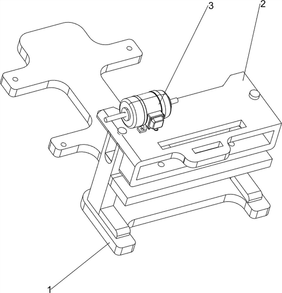
[0023] An iron plate continuous bending machine, such as Figure 1-2Shown, including the base 1, table 2, motor 3, bending mechanism 4 and pressing mechanism 5, base 1 right side with table 2, table 2 top front side with motor 3, motor 3 output shaft and table 2 connected to the bending mechanism 4, table 2 middle connected with the compression mechanism 5, pressing mechanism 5 and bending mechanism 4 connection.

[0024] When people need to bend the iron plate, start the motor 3, insert the iron plate into the bending mechanism 4 and the bottom of the pressing mechanism 5, the motor 3 output shaft rotation drives the bending mechanism 4 and the pressing mechanism 5 continuously rotate, so that the pressing mechanism 5 presses the iron plate, the bending mechanism 4 bends the iron plate, after the bending is successful, the iron plate can be taken out, and when the device is not needed, the motor 3 can be turned off.

Embodiment 2

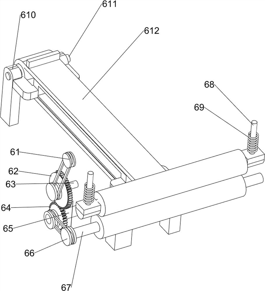
[0026] On the basis of Example 1, e.g., Figure 3 As shown, the bending mechanism 4 comprises a bevel gear assembly 41, a first belt set 42, a first drive shaft 43, a rotating disc 44, a long rod 45 and a press connection block 46, a bevel gear assembly 41 is connected between the motor 3 output shaft and the compression mechanism 5, the upper rotating type of the table 2 is connected to the first drive shaft 43, the first transmission shaft 43 is connected to the first belt group 42 between the left part and the compression mechanism 5, the first transmission shaft 43 is connected to the right part of the rotating disc 44, the rotary disc 44 is connected to the eccentric position rotation type connection to the long rod 45, Table 2 right sliding connection has a press connection block 46, press connection block 46 top and long rod 45 rotary connection.

[0027] When people need to bend the iron plate, start the motor 3, the motor 3 output shaft rotation to drive the bevel gear ass...

Embodiment 3

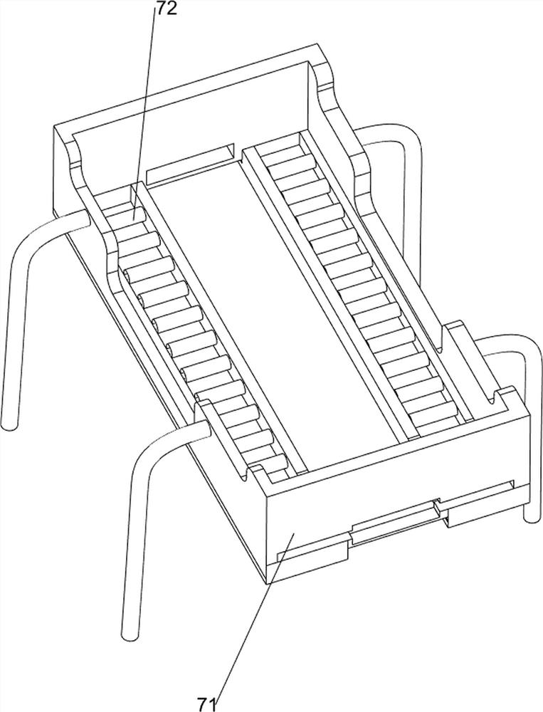
[0029] On the basis of Example 2, e.g., Figure 4-6As shown, the compression mechanism 5 includes a second drive shaft 51, a cam 52, a pressed joint 53 and a first compression spring 54, a table 2 lower side rotational connection with a second drive shaft 51, a second drive shaft 51 left and a bevel gear assembly 41 and a belt set 42 connected, a second drive shaft 51 connected to the right end of the cam 52, a table 2 right sliding connection with a compression joint block 53, a pressed joint 53 top with a cam 52 squeeze contact, The first compression spring 54 is connected between the upper part of the compression connection block 53 and the top of the table 2, the first compression spring 54 is set on the compression connection block 53.

[0030] After placing the iron plate in the middle of the table 2, the motor 3 output shaft rotation drives the bevel gear assembly 41, the second transmission shaft 51 and the cam 52 continue to rotate, when pressing the connecting block 46 do...


PUM


Abstract

The invention relates to a bending machine, in particular to a continuous bending machine for iron plates. Provide and develop a continuous iron plate bending machine that can fix the iron plate and realize the function of conveying the iron plate. The technical solution is: a continuous bending machine for iron plates, including a workbench on one side of the base; a motor, a motor on the top of the workbench; a bending mechanism, a bending mechanism connected between the output shaft of the motor and the workbench; The pressing mechanism is connected with the working table, and the pressing mechanism is connected with the bending mechanism. Through the cooperation between the motor and the bending mechanism, the effect of bending the iron plate can be realized without manual bending, which improves the work efficiency and quality. Through the cooperation of the pressing mechanism, the bending of the iron plate can be realized During the bending process, fix it to avoid errors during the bending process, resulting in product damage.

Description

Technical field [0001] The present invention relates to a bending machine, in particular to an iron plate continuous bending machine. Background [0002] At present, the industry is becoming more and more prosperous, the requirements for products are getting higher and higher, the diversity of products is crucial, and iron plates are indispensable in industrial production. Due to the needs of industrial production, the need to bend the iron plate, so that the use is more extensive, there is no special equipment to bend it, workers usually use bending iron rods, the iron plate is bent, due to the different thickness of the iron plate, it takes people to spend a lot of effort to complete, which will lead to people's body soreness, and time-consuming and laborious, the iron plate bending accuracy is low. [0003] Patent Application CN201910459762.0 A kind of curved iron plate bending machine, including organic frame, mounting frame, first motor, first pulley, missing gear, second pu...

Claims


Application Information

Patent Timeline
Patent Type & Authority Patents(China)
IPC IPC(8): B21D5/04B21D43/12B21D43/09B21D43/08B21D43/02
CPCB21D5/045B21D43/12B21D43/09B21D43/08B21D43/026Y02P40/57
Inventor 董丽霞
Owner ZHONGTIAN BROADBAND TECH
Why Eureka
Try Eureka