Steel bending forming device
A bending forming and steel technology, applied in forming tools, metal processing equipment, manufacturing tools, etc., can solve the problems of increased cost, unsatisfactory, high power equipment requirements, etc., and achieve the effect of strengthening the forming angle
- Summary
- Abstract
- Description
- Claims
- Application Information
AI Technical Summary
Problems solved by technology
Method used
Image
Examples
Embodiment 1
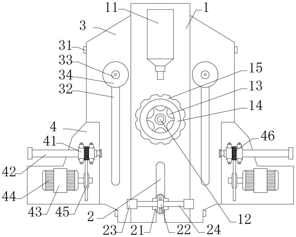
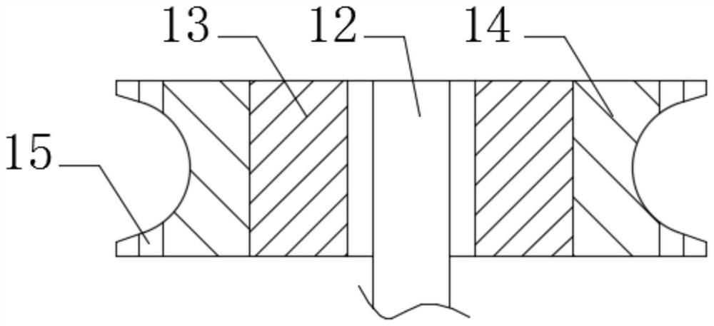
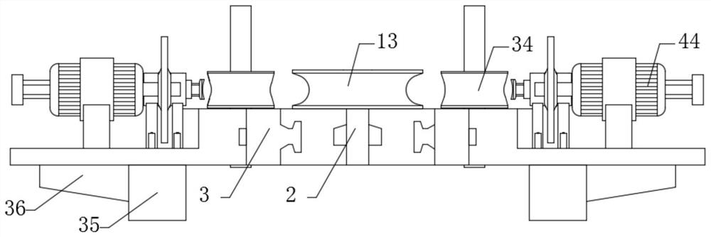
[0027] Please refer to Figure 1-3 ,in, figure 1 It is a schematic diagram of the overall top view of the present invention; figure 2 It is a schematic cross-sectional view of the central disk of the present invention; image 3 It is a schematic diagram of the overall front view structure of the present invention; a steel bending and forming device, including: a main board 1, a bracket 12 is socketed at the center of the main board 1, and a central disk 13 is welded on the periphery of the bracket 12. An electric heater 14 is welded on the periphery of the central disk 13 .
[0028] Wherein, during use, the setting of the electric heater 14 heats the inside bending place to prevent the stress of the steel material from producing a large amount of burrs, so that the bending effect is greatly increased.
[0029] Side plate 3, side plates 3 are clamped on both sides of the main board 1, a bending chute 32 is opened on the side plate 3, a handle 33 is slidably connected to the...
Embodiment 2
[0038] Please refer to Figure 1-3 ,in, figure 1 It is a schematic diagram of the overall top view of the present invention; figure 2 It is a schematic cross-sectional view of the central disk of the present invention; image 3 It is a schematic diagram of the overall front view structure of the present invention; a steel bending and forming device, including: a main board 1, a bracket 12 is socketed at the center of the main board 1, and a central disk 13 is welded on the periphery of the bracket 12. An electric heater 14 is welded on the periphery of the central disk 13 .
[0039] Wherein, during use, the setting of the electric heater 14 heats the inside bending place to prevent the stress of the steel material from producing a large amount of burrs, so that the bending effect is greatly increased.
[0040] Side plate 3, side plates 3 are clamped on both sides of the main board 1, a bending chute 32 is opened on the side plate 3, a handle 33 is slidably connected to the...
Embodiment 3
[0051] Please refer to Figure 1-3 ,in, figure 1 It is a schematic diagram of the overall top view of the present invention; figure 2 It is a schematic cross-sectional view of the central disk of the present invention; image 3 It is a schematic diagram of the overall front view structure of the present invention; a steel bending and forming device, including: a main board 1, a bracket 12 is socketed at the center of the main board 1, and a central disk 13 is welded on the periphery of the bracket 12. An electric heater 14 is welded on the periphery of the central disk 13 .
[0052] Wherein, during use, the setting of the electric heater 14 heats the inside bending place to prevent the stress of the steel material from producing a large amount of burrs, so that the bending effect is greatly increased.
[0053] Side plate 3, side plates 3 are clamped on both sides of the main board 1, a bending chute 32 is opened on the side plate 3, a handle 33 is slidably connected to the...
PUM
 Abstract
Description
Claims
Application Information
 - R&D
- Intellectual Property
- Life Sciences
- Materials
- Tech Scout
- Unparalleled Data Quality
- Higher Quality Content
- 60% Fewer Hallucinations
Browse by: Latest US Patents, China's latest patents, Technical Efficacy Thesaurus, Application Domain, Technology Topic, Popular Technical Reports.
© 2025 PatSnap. All rights reserved.Legal|Privacy policy|Modern Slavery Act Transparency Statement|Sitemap|About US| Contact US: help@patsnap.com


