Frame plate bending device for new energy automobile

A new energy vehicle, bending device technology, applied in the direction of feeding device, positioning device, storage device, etc., can solve the problem of manpower consumption, and achieve the effect of reducing manpower consumption, easy operation of manpower, and manpower saving.

Pending Publication Date: 2022-04-15
江玉婷
View PDF1 Cites 0 Cited by
  • Summary
  • Abstract
  • Description
  • Claims
  • Application Information

AI Technical Summary

Problems solved by technology

[0006] In order to overcome the shortcomings of the above-mentioned patents that frequent manual loading and unloading is required during the operation, and the operation is relatively labor-intensive, the technical problem to be solved by the present invention is to provide a method that does not require frequent manual loading and unloading during the operation. material and unloading, which can save manpower and is used for the bending device of new energy vehicle frame plate

Method used


Image

  • Frame plate bending device for new energy automobile
  • Frame plate bending device for new energy automobile
  • Frame plate bending device for new energy automobile

Examples


Embodiment 1

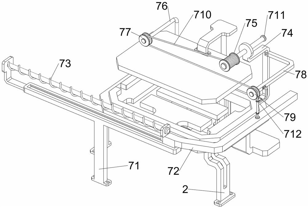
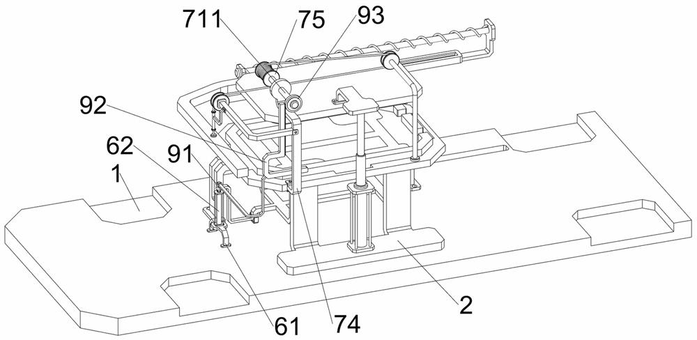
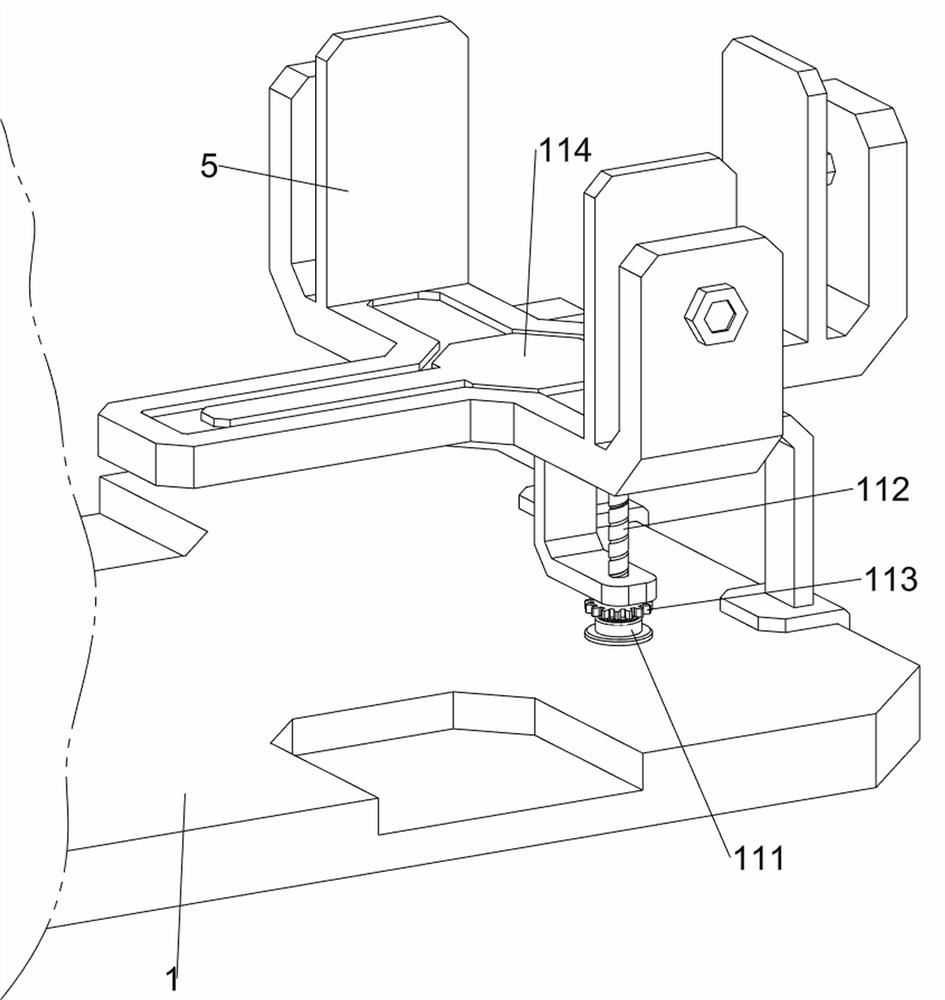
[0041] A bending device for new energy vehicle frame plates, such as Figure 1-5 As shown, it includes a base plate 1, a material setting table 2, a first cylinder 3, a bending plate 4, a storage rack 5, a material ejecting mechanism 6 and a material pushing mechanism 7, and a material setting table 2 is connected in the middle of the top of the bottom plate 1. Platform 2 is used to place frame plates, and a first air cylinder 3 is installed on the rear side of the material placing table 2, and a bending plate 4 is connected to the telescopic rod of the first air cylinder 3, which is used to bend the frame plates. The curved plate 4 is located above the material setting table 2, and the top right side of the bottom plate 1 is connected with a storage rack 5, the storage rack 5 is used to store the frame plate, and a lifting mechanism 6 is provided between the bottom plate 1 and the material setting table 2, and the material lifting mechanism 6 It is used to push out the bent f...

Embodiment 2

[0046] On the basis of Example 1, such as figure 1 , Figure 6 , Figure 7 and Figure 8 As shown, a positioning mechanism 8 is also included. The positioning mechanism 8 is used to position the frame plate. The positioning mechanism 8 includes a positioning plate 81, a first rack 82, a first gear 83, a second rack 84 and a third branch. Rod 85 is slidingly connected with a positioning plate 81 on the material setting table 2, and the positioning plate 81 is used to position the frame plate. The position of the bar 82 is connected with a third pole 85, and the third pole 85 is connected with a first gear 83 in a rotational manner, and the rear side of the bottom of the bending plate 4 is connected with a second rack 84, and the first rack 82 is connected with the first gear The left side of the gear 83 meshes, and the second rack 84 descends to mesh with the left side of the first gear 83 .

[0047] The bending plate 4 drives the second tooth bar 84 to move downward when m...

Embodiment 3

[0051] On the basis of Example 2, such as figure 1 , Figure 9 , Figure 10 , Figure 11 , Figure 12 , Figure 13 , Figure 14 and Figure 15 As shown, a collection mechanism 10 is also included, and the collection mechanism 10 is used to collect the bent frame plates. The collection mechanism 10 includes a third support plate 101, a collection frame 102, a second guide rail 103, a third rack 104, The second spring 105, the first bearing seat 106, the second gear 107, the first threaded rod 108, the connecting plate 109 and the push rod 1010; There is a first bearing seat 106, the first bearing seat 106 is rotationally connected with a first threaded rod 108, the bottom of the first threaded rod 108 is connected with a second gear 107, and the first threaded rod 108 is threadedly connected with a connecting plate 109, The front side of connecting plate 109 is connected with collecting frame 102, and collecting frame 102 is used for collecting the frame plate after bend...


PUM


Abstract

The invention relates to a bending device, in particular to a bending device for a new energy automobile frame plate. According to the bending device for the frame plate of the new energy automobile, in the operation process, manual frequent feeding and discharging are not needed, and manpower can be saved. The bending device for the new energy automobile frame plate comprises a bottom plate, and a material placing table is connected to the middle of the top of the bottom plate; the first air cylinder is mounted on one side of the material placing table; the bending plate is connected to a telescopic rod of the first air cylinder; one side of the top of the bottom plate is connected with the storage rack; the material ejecting mechanism is arranged between the bottom plate and the material placing table; and the material pushing mechanism is arranged between the bottom plate and the material placing table. A frame plate is placed through the material placing table, and after the frame plate is placed, the first air cylinder is started to drive the bending plate to move downwards to bend the frame plate, so that the effect of bending the frame plate is achieved.

Description

technical field [0001] The invention relates to a bending device, in particular to a bending device for a frame plate of a new energy vehicle. Background technique [0002] Cars are an important travel tool in people's lives in modern society, and new energy vehicles are a category of cars. New energy vehicles mainly use fuel cells, hybrid power or hydrogen energy to remove gasoline and diesel engines In the process of assembling new energy vehicles, it is usually necessary to bend the frame plates of new energy vehicles for better installation. [0003] After searching, the authorized patent publication number is CN213350300U, which discloses a plate bending machine for new energy vehicle frame processing, including a casing, the inner wall of the casing is fixedly connected with a baffle, and the bottom surface of the baffle is fixed. A placement plate is connected, the top surface of the placement plate is overlapped with a connection block, the side of the connection bl...

Claims


Application Information

Patent Timeline
IPC IPC(8): B21D11/10B21D11/22B21D45/04B21D43/22B21D43/24
Inventor 江玉婷
Owner 江玉婷
Why Eureka
Try Eureka