Automatic PT cabinet switching device for multipath incoming lines

An automatic switching and incoming line technology, applied in circuit devices, busbar/line layout, substation/distribution device housing, etc., can solve the problem of untimely circuit disconnection, unsecured safety, and multi-channel incoming PT cabinets. Unable to automatically switch and other problems to achieve the effect of improving reliability and ensuring safe use

Pending Publication Date: 2021-04-30
HEFEI SWITCH FACTORY
View PDF1 Cites 0 Cited by
  • Summary
  • Abstract
  • Description
  • Claims
  • Application Information

AI Technical Summary

Problems solved by technology

[0005] Aiming at the deficiencies of the prior art, the present invention provides an automatic switching device for PT cabinets for multi-channel incoming lines, which overcomes the deficiencies of the prior art, has a reasonable design and a compact structure, and aims to solve the problems of the existing multi-channel incoming PT cabinets. It is impossible to automatically switch the incoming line according to the actual situation, the circuit is not disconnected in time, the reliability of the power supply is low, and the safety cannot be guaranteed.

Method used


Image

  • Automatic PT cabinet switching device for multipath incoming lines
  • Automatic PT cabinet switching device for multipath incoming lines
  • Automatic PT cabinet switching device for multipath incoming lines

Examples


Embodiment 1

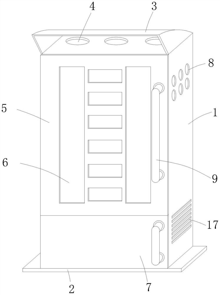
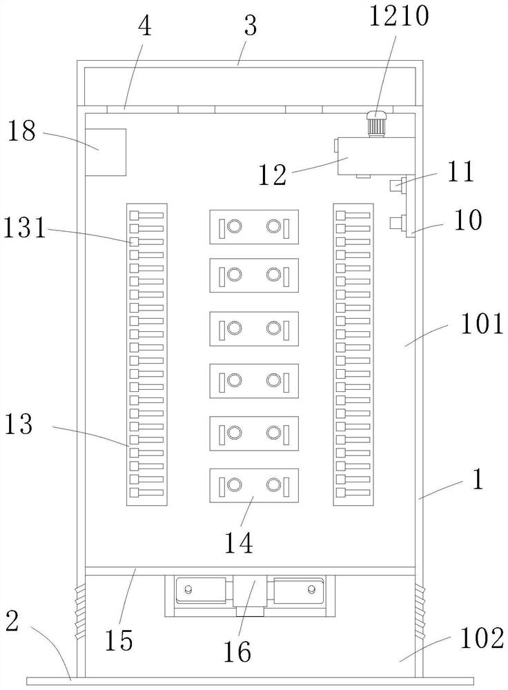
[0031] A PT cabinet automatic switching device for multiple incoming lines, comprising a hollow cabinet body 1 and a base 2 installed at the lower end of the cabinet body 1, the lower part of the inner cavity of the cabinet body 1 is horizontally equipped with a porous partition plate 15, and the porous The partition plate 15 divides the inner cavity of the cabinet body 1 from top to bottom into an installation cavity 101 and a heat dissipation cavity 102. The front wall of the cabinet body 1 corresponding to the positions of the installation cavity 101 and the heat dissipation cavity 102 is respectively provided with an upper cabinet door 5 and a Lower cabinet door 7;

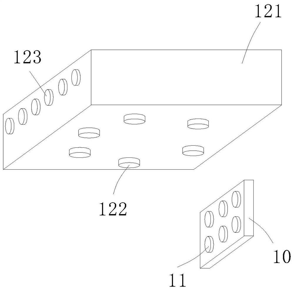
[0032] In this example, if Figure 1-2 As shown, on the side wall of the cabinet body 1 corresponding to the position of the installation cavity 101, there are a plurality of inlets 8 for multiple incoming lines to pass through, and a terminal block 10 is installed on the inner wall of the installation cavity ...

Embodiment 2

[0038] The difference between this embodiment and embodiment 1 is that, as Figure 1-2 As shown, a plurality of exhaust outlets 4 are provided on the top wall of the cabinet body 1, and an air intake grid 17 is provided on the side wall of the cabinet body 1 corresponding to the position of the cooling chamber 102, and an inner cavity of the cooling chamber 102 is provided with There is a heat dissipation fan 16 with the output end facing upwards. The air inlet grid 17 is provided with two groups and is respectively symmetrically embedded on the opposite side walls of the cabinet 1 to ensure the cooling of the air intake. The grid is arranged downwards from the inside to the outside to prevent external rainwater from entering the inner cavity of the cabinet body 1. A ceiling 3 with a front opening is installed on the top wall of the cabinet body 1, and the ceiling 3 is inclined from the front to the rear. Downward setting prevents external rainwater from entering the inner cavit...


PUM


Abstract

The invention relates to the technical field of power equipment, provides an automatic PT cabinet switching device for multi-path incoming lines, and aims to solve the problems that an existing PT cabinet for multi-path incoming lines cannot automatically switch incoming lines according to actual conditions, a circuit is not disconnected in time, the power supply reliability is low, and the safety cannot be guaranteed. The device comprises a hollow cabinet body and a base installed at the lower end of the cabinet body, wherein a porous partition plate is horizontally installed at the lower portion of an inner cavity of the cabinet body and divides the inner cavity of the cabinet body into an installation cavity and a heat dissipation cavity from top to bottom in sequence; an upper cabinet door and a lower cabinet door are arranged on the front wall, corresponding to the installation cavity and the heat dissipation cavity, of the cabinet body; the side wall of the cabinet body corresponding to the position of the installation cavity is provided with a plurality of wire inlets through which a plurality of inlet wires pass. The device is especially suitable for safe use of the PT cabinet with multiple incoming lines, and has high social use value and application prospect.

Description

technical field [0001] The invention relates to the technical field of electric power equipment, in particular to an automatic switching device for a PT cabinet for multiple incoming lines. Background technique [0002] The PT cabinet is the voltage transformer cabinet, which is generally installed directly on the busbar to detect the busbar voltage and realize the protection function. It mainly installs the voltage transformer PT, isolating knife, fuse and lightning arrester inside. The PT cabinet adopts a combined structure, and different quantities and types of PTs can be configured according to specific projects. The existing PT cabinet with multiple incoming lines cannot automatically switch the incoming lines according to the actual situation, the circuit is not disconnected in time, the reliability of the power supply is low, and the safety cannot be guaranteed. [0003] The patent with the publication number CN211351818U discloses an AC power supply interlocking dev...

Claims


Application Information

Patent Timeline
Patent Type & Authority Applications(China)
IPC IPC(8): H02B1/20H02B1/56H02B1/28H02J3/00
CPCH02B1/20H02B1/28H02B1/565H02J3/007
Inventor 王球锋谢金龙谢法金伯彩云孙阿欢崔健房玉祥郝会
Owner HEFEI SWITCH FACTORY
Why Eureka
Try Eureka