An emergency separation device

A separation device and separation piece technology, applied in the field of emergency separation, can solve the problems of low safety, poor reliability and high cost, and achieve the effects of convenient use, high reliability and simple device

Active Publication Date: 2022-06-28
XIAN AIRCRAFT DESIGN INST OF AVIATION IND OF CHINA
View PDF11 Cites 0 Cited by
  • Summary
  • Abstract
  • Description
  • Claims
  • Application Information

AI Technical Summary

Problems solved by technology

[0002] In terms of emergency separation between equipment, there are many structural forms at home and abroad. Generally, the form of fixed parts is used. When emergency separation is required, the broken fixed parts are used to achieve emergency separation. This structure has low safety, poor reliability, relatively high cost, and is economical. Poor, and easily restricted by external conditions

Method used


Image

  • An emergency separation device
  • An emergency separation device
  • An emergency separation device

Examples


Embodiment Construction

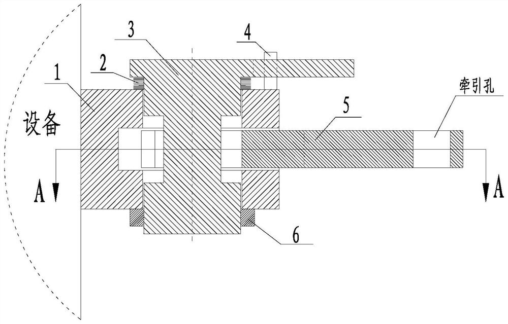
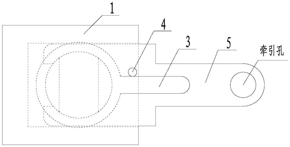
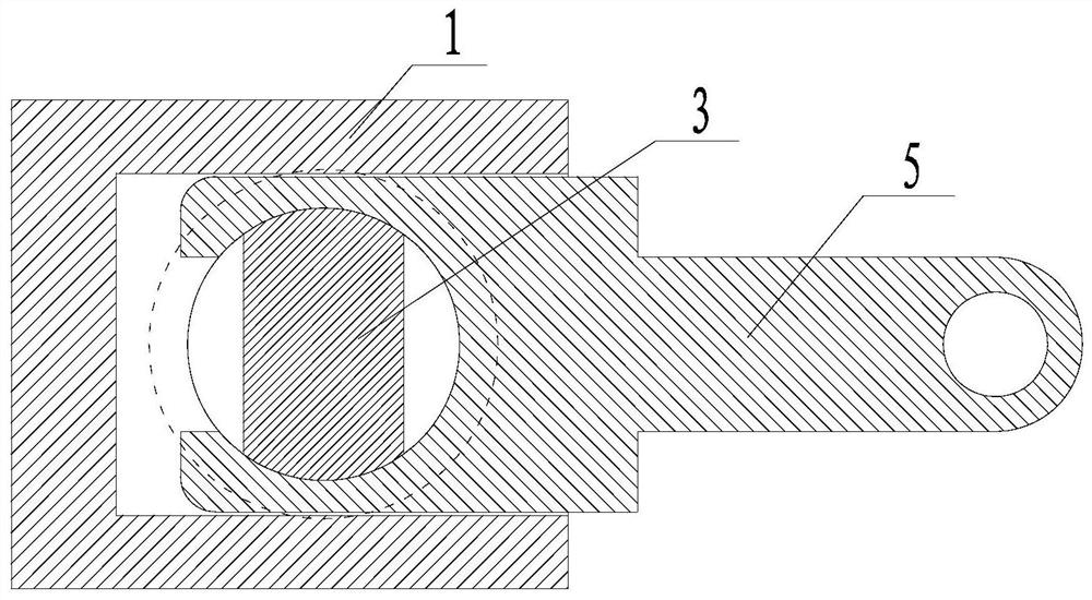
[0012] Below in conjunction with accompanying drawing, the present invention is described in further detail:

[0013] like figure 1 , 2 As shown in , 3, an emergency separation device includes a mounting seat 1, a torsion spring 2, a connecting piece 3, a limit block 4, a separating piece 5 and a nut 6. The installation base 1 is a rectangular body, the left end face of the installation base 1 is fixed on the equipment, a circular through hole is opened from top to bottom in the middle of the upper surface of the installation base 1, and a rectangular blind hole is opened at the right end of the installation base 1 to the left. And through the circular through hole, the upper end of the connecting piece 3 is a round cake body, the lower part of the connecting piece 3 is a cylindrical body, and a cantilever rod is provided at the right end of the round cake body at the upper end of the connecting piece 3, and the cylindrical body of the connecting piece 3 is There are two rec...


PUM


Abstract

The invention relates to the technical field of emergency separation, in particular to an emergency separation device. Among them, the left end surface of the installation bottom [1] is fixed on the equipment, and a cantilever rod is arranged at the right end of the upper end of the connecting piece [3], and there are two symmetrical openings on the left and right sides of the middle of the cylinder of the connecting piece [3]. A rectangular slot, the cylinder of the connector [3] is placed in the circular through hole of the installation bottom [1], the lower end of the cylinder of the connector [3] exposes the lower surface of the installation bottom [1], and the torsion spring [2] is set on On the cylinder of the connecting piece [3], the nut [6] fixes the connecting piece [3] in the circular through hole of the installation bottom [1], and the left part of the separation piece [5] is placed in the rectangular blind hole of the installation bottom [1] , and make the middle part of the cylinder of the connector [3] in the circular through hole of the separator [5], and the limit block [4] is affixed to the right end of the upper surface of the installation bottom [1]. The front surface of the limit block [4] is attached to the rear surface of the cantilever rod of the connector [3]. The invention integrates the emergency separation into a simple device, reduces the cost and has high reliability.

Description

technical field [0001] The invention relates to the technical field of emergency separation, in particular to an emergency separation device. Background technique [0002] In terms of emergency separation between equipment, there are many structural forms at home and abroad, generally in the form of fasteners, and when emergency separation is required, the destruction of fasteners is used to achieve emergency separation, which has low structural safety, poor reliability, high cost, and economical It has poor performance and is easily restricted by external conditions. SUMMARY OF THE INVENTION [0003] The purpose of this invention is: [0004] The present invention provides an emergency separation device for emergency separation between devices, which can be applied to emergency separation between devices. [0005] The technical scheme of the present invention is: [0006] An emergency separation device comprises a mounting seat 1, a torsion spring 2, a connecting piece...

Claims


Application Information

Patent Timeline
Patent Type & Authority Patents(China)
IPC IPC(8): F16B13/10F16G11/00
CPCF16B13/04F16G11/00
Inventor 张恒铭
Owner XIAN AIRCRAFT DESIGN INST OF AVIATION IND OF CHINA
Why Eureka
Try Eureka