Binding tool

A technique of utensils and postures, which is applied in the field of binding utensils and can solve the problems of constraints of binding utensils, large size of binding utensils, etc.

Inactive Publication Date: 2021-05-07
KOKUYO COMMERCE (SHANGHAI) CO LTD
View PDF1 Cites 0 Cited by
  • Summary
  • Abstract
  • Description
  • Claims
  • Application Information

AI Technical Summary

Problems solved by technology

Furthermore, because the operating lever is arranged on the side of the binding appliance, the overall size of the binding appliance will become large, and certain restrictions will be placed on the setting of the binding appliance.

Method used


Image

  • Binding tool
  • Binding tool
  • Binding tool

Examples


Embodiment Construction

[0039] Specific embodiments of the present invention will be described below with reference to the accompanying drawings. In the following description, for convenience of description, the side of the binding tool T, such as a binding paper, is referred to as the front side, and the opposite side is referred to as the rear side.

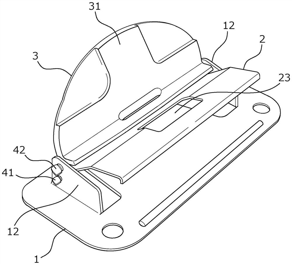
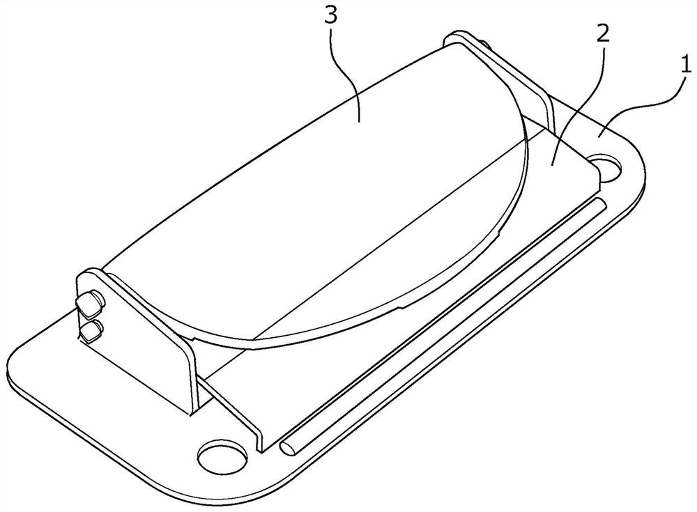
[0040] Such as figure 1 As shown, the binding tool T of the present embodiment mainly has a base 1, a clamping part 2, an operating part 3, a first rotating shaft 41, a second rotating shaft 42 and a spring 43 (refer to Figure 10 , Figure 11 ).

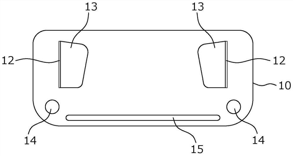
[0041] The base 1 is formed by punching a sheet metal. Such as image 3 and Figure 4 As shown, the base 1 is generally rectangular in plan view, and the four corners are rounded. The base 1 has a rectangular base main body 10 in plan view, and two supporting parts 12 parallel to each other and perpendicular to the base main body 10 . The two support portions 12 are formed by punching the base body p...


PUM


Abstract

The invention provides a binding tool which is small and easy to operate. The binding tool is provided with a clamping component and an operating component, wherein the clamping component is provided with a first rotating shaft, can be in an opening posture and a binding posture, and clamps and holds a bound object in the binding posture; and the operating component is provided with a second rotating shaft, is rotatable between a pressing posture in which the clamping component is pressed and a pressing release posture, and can be operated into the pressing posture to hold the clamping component in the binding posture.

Description

technical field [0001] The invention relates to a binding appliance, in particular to a binding appliance for binding objects without openings. Background technique [0002] As a binding tool for binding objects without perforations, there is the binding tool described in Patent Document 1. The binding tool deforms the spring by operating the operating lever to generate elastic force to press the objects to be bound such as paper, and by turning the The lever is locked to maintain this pressed state. In the binding tool described in Patent Document 1, in order to obtain a large pressing force to stably press the bound object such as paper, it is necessary to use a spring with a large elastic force. In particular, when the amount of objects to be bound is large, since the amount of deformation of the spring is large, the force required for the operation becomes correspondingly large. In this way, in the actual operation process, it is necessary to use a relatively large for...

Claims


Application Information

Patent Timeline
Patent Type & Authority Applications(China)
IPC IPC(8): B42F9/00
CPCB42F9/001
Inventor 岩津博文
Owner KOKUYO COMMERCE (SHANGHAI) CO LTD
Why Eureka
Try Eureka