Fire-fighting fire extinguishing hydrant box c
A fire hydrant and firefighting technology, applied in fire rescue and other directions, can solve problems such as affecting the normal breathing of firefighters, and achieve the effect of facilitating daily fire inspections, enhancing fire, and avoiding waste.
- Summary
- Abstract
- Description
- Claims
- Application Information
AI Technical Summary
Problems solved by technology
Method used
Image
Examples
Embodiment 1
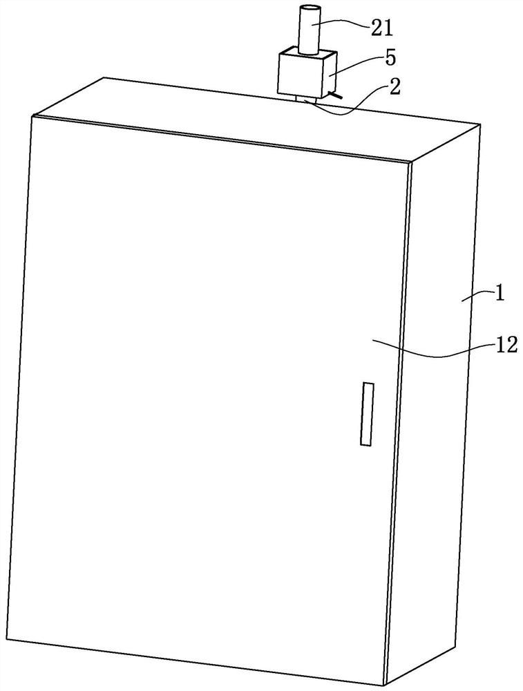
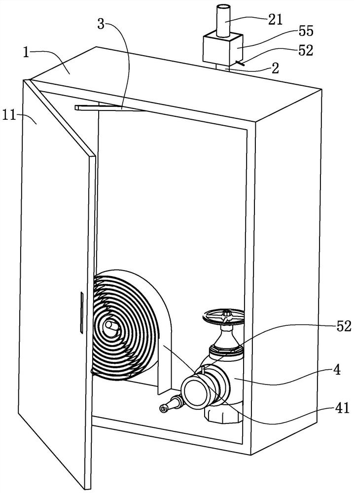
[0038] refer to figure 1 , discloses a fire hydrant box for this application, including a box shell 1 fixedly embedded in the wall, the box shell 1 is a rectangular shell, and the surface of the box shell 1 that is flush with the wall is provided with an opening. A fire-fighting cover 11 that covers its opening is hinged, and a button bounce lock is provided between the fire-fighting cover 11 and the case shell 1 to maintain a stable connection between the fire-fighting cover 11 and the case shell 1 after it is closed.
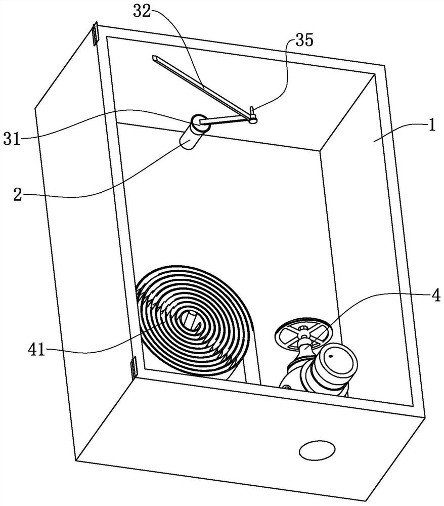
[0039] refer to figure 2 , a fire hydrant 4 is fixed inside the box shell 1, and one end structure of the fire hydrant 4 is connected to the fire-fighting water supply pipe in the building. The pipeline 41 and the fire-fighting pipeline 41 are usually coiled and placed in the casing 1 . When the fire hydrant 4 needs to be used, the fire cover 11 is opened, the fire pipe 41 is quickly connected to the water gun, the switch on the fire hydrant 4 is opened, an...
Embodiment 2
[0051] refer to Figure 5 , a fire hydrant box, the difference from Embodiment 1 is that the blocking mechanism 3 includes a guide plate 36 fixed to the inner cavity of the box shell 1, the guide plate 36 is a square plate, and the guide plate 36 is provided with an axis and an air supply The joint 2 extends into the circular hole where the ports of the inner cavity of the box shell 1 coincide. The guide plate 36 is pierced with a slide bar 33, the slide bar 33 is a round bar that slides along its axial direction, the slide bar 33 is fixedly provided with a drive plate 37, the drive plate 37 is a square plate, and the drive plate 37 is located at the back of the guide plate 36. To the side of the air supply joint 2.
[0052] The sliding rod 33 is covered with a driving spring 34, the driving spring 34 is a compression spring, and the two ends of the driving spring 34 are respectively pressed against the guide plate 36 and the driving plate 37, and the driving spring 34 drives...
PUM
 Abstract
Description
Claims
Application Information
 - R&D
- Intellectual Property
- Life Sciences
- Materials
- Tech Scout
- Unparalleled Data Quality
- Higher Quality Content
- 60% Fewer Hallucinations
Browse by: Latest US Patents, China's latest patents, Technical Efficacy Thesaurus, Application Domain, Technology Topic, Popular Technical Reports.
© 2025 PatSnap. All rights reserved.Legal|Privacy policy|Modern Slavery Act Transparency Statement|Sitemap|About US| Contact US: help@patsnap.com


