A gridded rock mass stress and vibration monitoring device, auxiliary installation device, and installation and use method based on pipe-slit bolts
An installation device and pipe-slit technology, which is applied in the field of grid-type rock mass stress and vibration monitoring devices, can solve problems such as low intelligence, inability to simultaneously collect multi-parameter data, and single function, so as to improve safety , excellent support performance, and the effect of increasing accuracy
- Summary
- Abstract
- Description
- Claims
- Application Information
AI Technical Summary
Problems solved by technology
Method used
Image
Examples
Embodiment 1
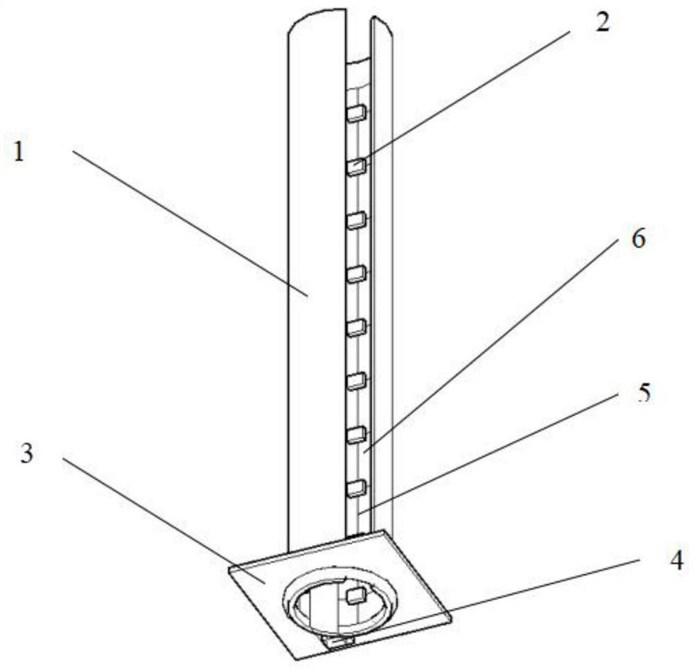
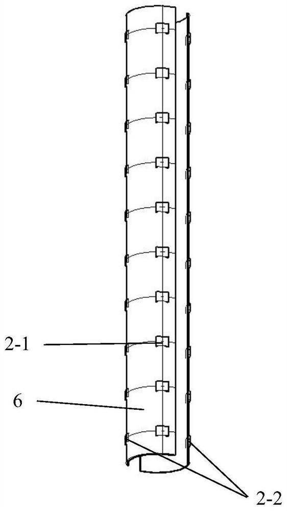
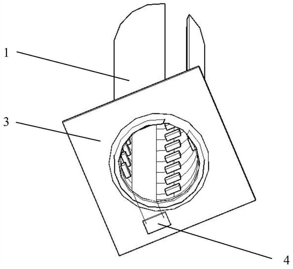
[0045] Such as Figure 1-3 As shown, this embodiment provides a grid-type rock mass stress and vibration monitoring device based on a pipe-slit bolt, which is characterized in that it includes a pipe-slit bolt body 1, a strain and vibration sensor integrated grid 2 , silicone jacket 6, fixed tray 3, information intelligent integration device 4, wired transmission unit 5, the strain and vibration sensor integration grid 2 is composed of multiple high-precision strain sensors 2-1 and two vibration sensors 2 -2 components, the main body of the grid is the strain sensor 2-1 evenly and symmetrically distributed at a certain distance from top to bottom, and the two vibration sensors 2-2 are arranged at the symmetrical position of the drilling hole, and the sensors are transmitted by wires The fixed tray 3 is installed at the contact between the bottom of the pipe-slotted bolt and the rock wall. There are small holes on the tray for strengthening the surrounding rock, and it is also ...
Embodiment 2
[0050] This embodiment provides an auxiliary installation device for installing the strain and vibration sensor integrated grid to the pipe-slotted bolt that has been driven into the borehole, and the auxiliary installation device can be applied to one of the first embodiments The installation of a grid-type rock mass stress and vibration monitoring device based on a pipe-slit bolt, such as Figure 4-14 As shown, the auxiliary installation device includes a grid carrier, a movable support rod 8, a sleeve 9, a central rod 10, a fastening bolt 11, a device fixing body, an L-shaped semi-hollow cylinder 13, a spring 14, and a sleeve stopper. Plate and threaded knob 23, the grid carrier is used as the installation carrier of the integrated grid of the strain and vibration sensor, and is composed of two symmetrical hollow semi-cylindrical shapes 7-1 and 7-2, and the fixed body of the device is located on the grid The upper and lower ends of the carrier body are composed of two cylin...
Embodiment 3
[0058] This embodiment provides a method for installing and using a grid-type rock mass stress and vibration monitoring device based on a pipe-slit bolt in Embodiment 1, which is characterized in that it mainly includes the following steps:
[0059] Step 1: According to the actual situation and needs of the mine, use the rock drilling rig to drill holes with the required diameter and depth at a reasonable interval.
[0060] Step 2: Use the anchor grinding device to grind and polish the inner wall of the slotted anchor, so that when the strain and vibration sensor integrated grid 2 is installed, it is more conducive to the tight fit between the grid and the inner wall of the anchor.
[0061] Step 3: Perform linkage debugging and calibration before on-site installation of the strain and vibration sensor integrated grid 2 and the information intelligent integration device 4 to ensure that the entire signal receiving device can operate normally.
PUM
 Abstract
Description
Claims
Application Information
 - R&D
- Intellectual Property
- Life Sciences
- Materials
- Tech Scout
- Unparalleled Data Quality
- Higher Quality Content
- 60% Fewer Hallucinations
Browse by: Latest US Patents, China's latest patents, Technical Efficacy Thesaurus, Application Domain, Technology Topic, Popular Technical Reports.
© 2025 PatSnap. All rights reserved.Legal|Privacy policy|Modern Slavery Act Transparency Statement|Sitemap|About US| Contact US: help@patsnap.com


