Intermediate case test load loading device

A loading device and intermediary technology, which is applied in the direction of measuring device, testing material strength by applying stable torsion force, testing material strength by applying repetitive force/pulsation force, etc., can solve the problem of difficult to achieve precise positioning of actuator and limit intermediary casing Application of section bending moment and axial load loading capacity, deviation of section bending moment and axial load, etc.

Pending Publication Date: 2021-05-14
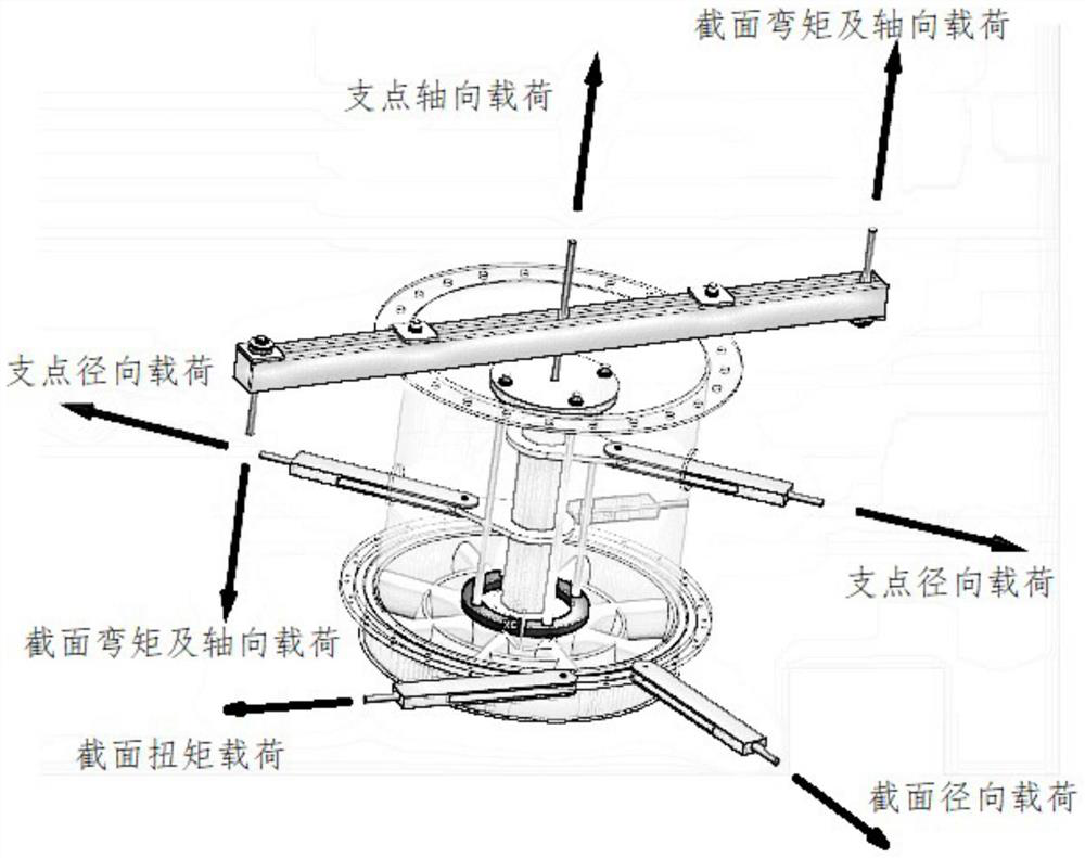
AECC SHENYANG ENGINE RES INST
View PDF11 Cites 4 Cited by
  • Summary
  • Abstract
  • Description
  • Claims
  • Application Information

AI Technical Summary

Problems solved by technology

[0009] 1) The two points of the transfer beam are connected to the end face of the transfer barrel, and a large stress will be generated at the connection part, which limits the loading capacity of the section bending moment and axial load applied to the intermediary casing, and cannot be adjusted continuously The angle of the transfer beam causes deviations in the section bending moments and axial loads applied to the intermediate casing at certain angles;
[0010] 2) The specific position of the fulcrum radial transfer hole on the adapter barrel needs to be opened according to the specific test conditions. When performing tests under different conditions, it is often necessary to add different fulcrum radial transfer holes on the transfer barrel , does not have universality, and it will consume a lot of manpower and material resources when conducting tests under different working conditions, and setting too many fulcrum radial transfer holes on the adapter barrel will seriously damage the strength of the adapter barrel, causing the adapter barrel to fail. It can further meet the strength requirements for applying loads to the intermediate casing;
[0013] 5) In order to apply a fulcrum axial load to the intermediate casing through the fulcrum axial loading joint, it is necessary to build a gantry-type frame spanning the entire device to install an actuator that can generate a fulcrum axial load connected to the fulcrum axial loading joint , the workload is large, and it is difficult to realize the precise positioning of the actuator, and it is difficult to ensure the effectiveness of the fulcrum axial load loading

Method used


Image

  • Intermediate case test load loading device
  • Intermediate case test load loading device
  • Intermediate case test load loading device

Examples


Embodiment Construction

[0052] In order to make the technical solution of the present application and its advantages clearer, the technical solution of the present application will be further clearly and completely described in detail below in conjunction with the accompanying drawings. It can be understood that the specific embodiments described here are only part of the application Examples are only used to explain the present application, not to limit the present application. It should be noted that, for the convenience of description, only the parts related to the present application are shown in the drawings, and other relevant parts can refer to the general design. In the case of no conflict, the embodiments in the application and the technologies in the embodiments Features can be combined with each other to obtain new embodiments.

[0053]In addition, unless otherwise defined, the technical terms or scientific terms used in the description of the application shall have the usual meanings unde...


PUM


Abstract

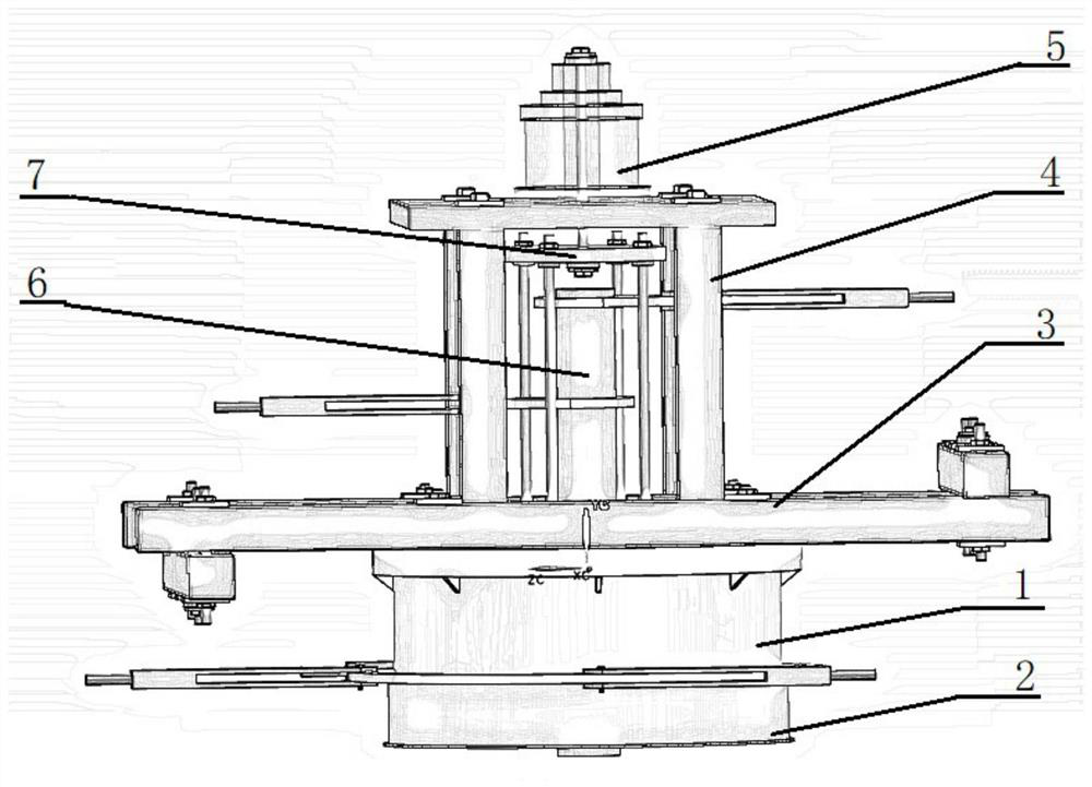
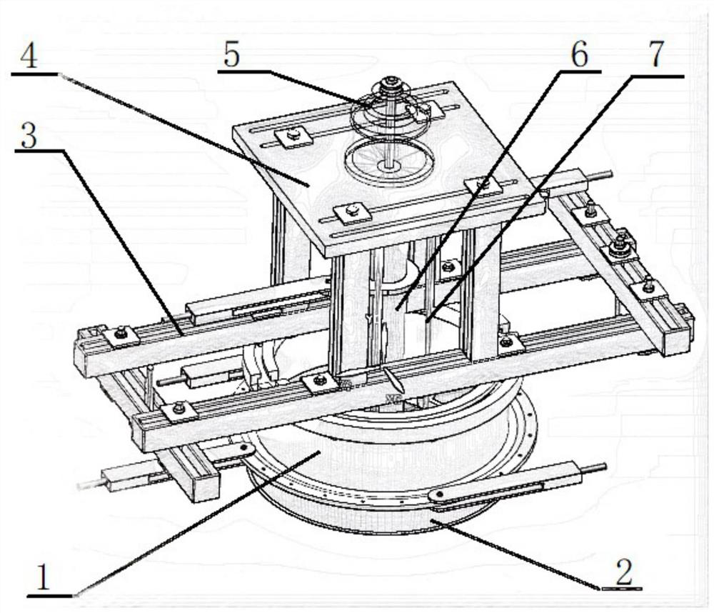
An intermediate case test load loading device comprises: an adapter cylinder, wherein one end of the adapter cylinder is in butt joint with an intermediate case, and the outer wall of the end is connected with a section torque loading connector and a section radial loading connector so as to apply section torque and radial load to the intermediate case; a switching frame connected with the end face of the other end of the switching cylinder, wherein two section bending moment and axial loading joints are connected to the switching frame so as to apply section bending moment and axial load to the intermediate case; a bearing frame connected to the switching frame, wherein a fulcrum axial load actuator is positioned and mounted on the bearing frame; a switching shaft, one end of the switching shaft is connected with a fulcrum part in the intermediate case, the other end of the switching shaft extends out of the switching cylinder, and the outer wall of the end is connected with a fulcrum radial loading joint so as to apply a fulcrum radial load to the intermediate case; and a switching rack arranged on the periphery of the switching shaft in a sleeving manner, connected with the fulcrum part in the intermediate case, ans connected with a fulcrum axial loading joint. The fulcrum axial loading joint is connected with the fulcrum axial load actuator so as to apply a fulcrum axial load to the intermediate case.

Description

technical field [0001] The application belongs to the technical field of loading design of intermediate casing test loads, and in particular relates to an intermediate casing test load loading device. Background technique [0002] To carry out static and fatigue tests on the intermediate casing of an aero-engine, it is necessary to apply bending moment, torque, axial, radial and other loads on the section of the intermediate casing, and to apply axial and radial loads on its fulcrum. [0003] When carrying out static and fatigue tests on the intermediate case of aero-engines, currently, such as figure 1 The test load loading device of the intermediate case loads the test load, including: [0004] The adapter barrel, one end is used to dock with the intermediate casing, the outer wall of this end is connected with a cross-section torque loading joint and a cross-section radial loading joint, so as to be able to apply cross-sectional torque and radial load to the intermediate...

Claims


Application Information

Patent Timeline
Patent Type & Authority Applications(China)
IPC IPC(8): G01N3/22G01N3/08G01N3/04G01N3/32
CPCG01N3/22G01N3/08G01N3/04G01N3/32G01N2203/0026G01N2203/0073G01N2203/0423
Inventor 刘韬刘伟强田常棵
Owner AECC SHENYANG ENGINE RES INST
Why Eureka
Try Eureka