
A kind of lock cylinder and lockset

A technology of lock cylinder and lock cylinder, which is applied in the field of locks and can solve problems such as low security

Active Publication Date: 2022-04-29
ZHUHAI UNITECH POWER TECH CO LTD
View PDF0 Cites 0 Cited by
  • Summary
  • Abstract
  • Description
  • Claims
  • Application Information

AI Technical Summary

Problems solved by technology

[0003] The embodiment of the present application provides a lock cylinder and a lock to improve the problem of low security of the existing blade lock cylinder

Method used


Image

  • A kind of lock cylinder and lockset
  • A kind of lock cylinder and lockset
  • A kind of lock cylinder and lockset

Examples


Embodiment

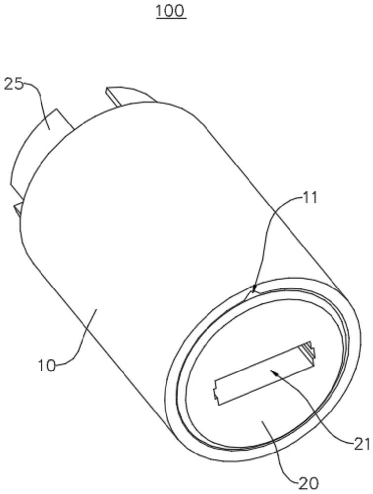
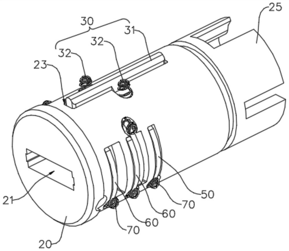
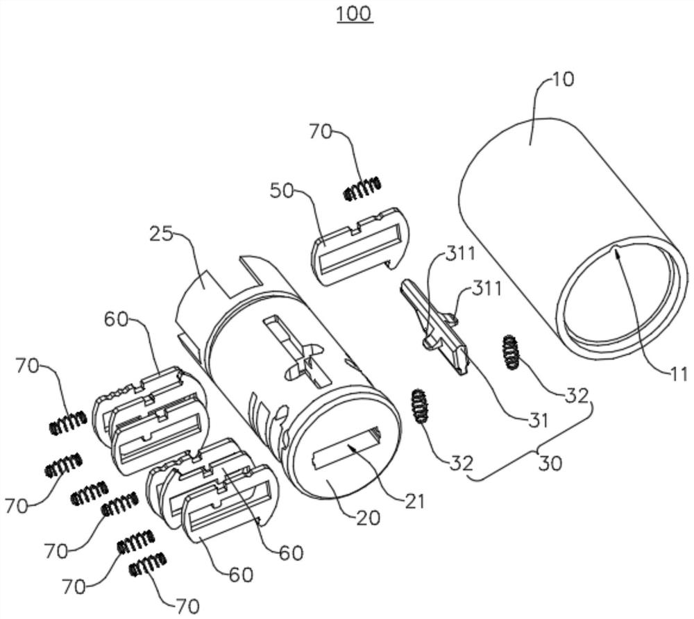
[0044] The embodiment of the present application provides a lock cylinder 100, which can improve the problem that the existing lock cylinder is very easy to be opened by thieves, resulting in extremely low security of the existing lock cylinder. The following describes the lock cylinder 100 in conjunction with the accompanying drawings. The specific structure is described in detail.

[0045] combine figure 1 , figure 2 and image 3 As shown, the lock cylinder 100 includes a lock case 10 , a lock cylinder 20 , a locking mechanism 30 and a plurality of blades. The lock cylinder 20 is rotatably disposed in the lock housing 10, and the lock cylinder 20 is provided with a lock hole 21 for inserting a key 40 (not shown in the figure). The locking mechanism 30 has a locked state that prevents the lock cylinder 20 from rotating and an unlocked state that allows the lock cylinder 20 to rotate. Each leaf is movably disposed on the cylinder 20, and each leaf has a locked position an...


PUM


Abstract

The application provides a lock cylinder and a lock, belonging to the technical field of locks. The lock cylinder includes a lock case, a lock cylinder, a locking mechanism and a plurality of blades. The lock cylinder is rotatably arranged in the lock case, and the lock cylinder is provided with a lock hole for a key to be inserted into. The locking mechanism has a locked state that prevents the lock cylinder from rotating and an unlocked state that allows the lock cylinder to rotate. Each leaf is movably arranged on the cylinder, and each leaf has a locking position and an unlocking position. When at least one blade is in the locked position, the locking mechanism is in the locked state. When the key is inserted into the lock hole, the key can push each blade to move to the unlocked position, so as to switch the locking mechanism from the locked state to the unlocked state. The multiple blades include at least one first blade, and a first limiting slot for the movement of the first blade is opened on the hole wall of the locking hole, and the first blade is hidden in the first limiting slot. The lock cylinder with this structure avoids direct contact between the first blade and the outside, making the lock cylinder difficult to be pried open, thus improving the safety of the lock cylinder.

Description

technical field [0001] The present application relates to the technical field of locks, in particular, to a lock cylinder and a lock. Background technique [0002] The blade lock cylinder is a kind of lock cylinder. The principle of the blade lock cylinder is to use the tooth flower grooves with different widths on the key to align the blades with different positions in the blade lock cylinder, so as to realize the rotation and opening of the lock cylinder. The blades of the blade lock cylinder in the prior art are usually provided with lock teeth, and the lock teeth are located in the lock hole of the lock cylinder. When the key is inserted into the lock hole, the lock teeth of the blade can be inserted into the tooth flower groove of the key Inside, the blade is driven to move in the lock cylinder through the tooth flower groove of the key, so as to realize the unlocking of the blade lock cylinder. However, the locking method of the current blade lock cylinder is known to...

Claims


Application Information

Patent Timeline
Patent Type & Authority Patents(China)
IPC IPC(8): E05B29/10E05B15/14E05B15/00E05B19/06
CPCE05B29/0033E05B15/14E05B15/00E05B19/0017
Inventor 李启平杨绍华何海雄李保福许海丰
Owner ZHUHAI UNITECH POWER TECH CO LTD
Learn More