

Counter balance leveled by using communicating vessels
A pallet balance and connector technology, applied in the field of balance, can solve problems such as impact, shortening the life of the balance, and time-consuming
- Summary
- Abstract
- Description
- Claims
- Application Information
AI Technical Summary
Problems solved by technology
Method used
Image

Examples
Embodiment 1
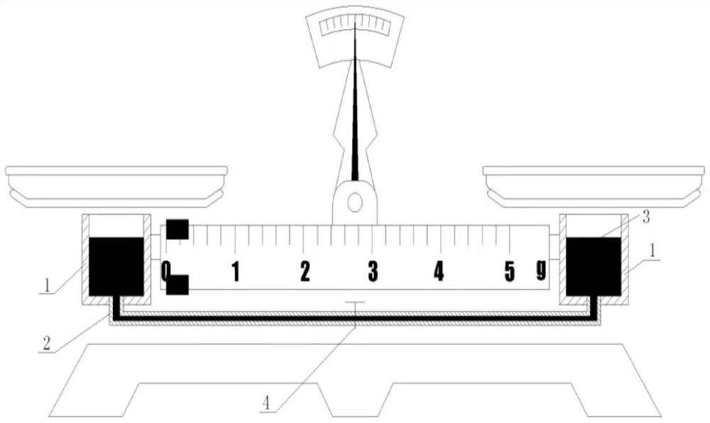
[0012] Embodiment 1 (see figure 1 ).
[0013] 1. The connecting device (including the container 1 and the pipeline 2) is arranged symmetrically at both ends of the tray balance lever, and the manual liquid valve 4 is arranged in the middle of the pipeline 2.
[0014] 2. When the pointer of the unbalanced balance exceeds the scale range of the dial, gently press (or lift) the lever, lower the high end to the lowest point, and then make the manual liquid valve 4 fully open, and close it after a few seconds Valve 4, observe the pointer position.
[0015] 3. When the pointer of the balance is in the scale range of the dial, gently press (or lift) the lever, point the pointer to the same scale in the opposite direction, and then make the manual liquid valve 4 half open, and close the valve 4 after a few seconds , observe the pointer position.
[0016] 4. Repeat the above steps until the balance is balanced.
Embodiment 2
[0017] Embodiment 2 (see figure 1 , figure 2 , image 3 ).
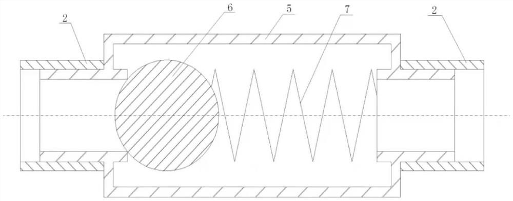
[0018] 1. Replace the manual liquid valve 4 of Embodiment 1 with a magnetic liquid valve 5 .
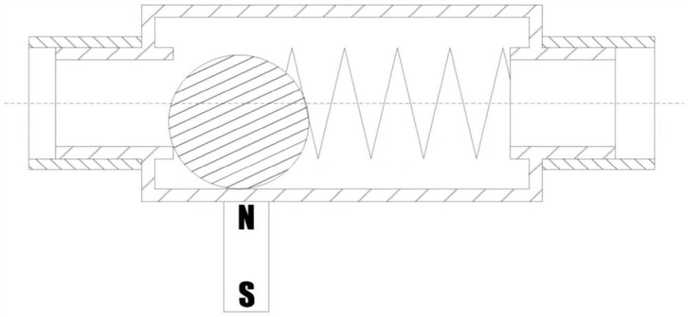
[0019] 2. When the pointer of the unbalanced balance exceeds the scale range of the dial, gently press (or lift) the lever, lower the high end to the lowest point, and then use the magnetic pole of the external magnetic object to attract (or repel) the valve at the nearest place The magnetic object 6 inside 5 makes the valve 5 fully open, remove the external magnetic object after a few seconds, close the valve 5, and observe the pointer position.
[0020] 3. When the pointer of the balance is within the scale range of the dial, gently press (or lift) the lever, point the pointer to the equal scale in the opposite direction, and then use the magnetic pole of the external magnetic object to attract (or repel) the valve at a little distance 5 The inner magnetic object 6 keeps the valve 5 in a half-open state, remove the o...
Embodiment 4
[0022] Embodiment 4 (see Figure 4 ).
[0023] 1. The connecting device (including the container 1 and the pipeline 2) is arranged symmetrically at both ends of the tray balance lever, and the container 1 at one end is a closed structure, and the valve 8 is set above the liquid level. When the valve 8 is opened, the liquid 3 can be in the Flow in the pipeline, when the valve 8 is closed, the liquid 3 no longer flows.
[0024] 2. When the pointer of the unbalanced balance exceeds the scale range of the dial, gently press (or lift) the lever to lower the high end to the lowest point, then open the valve 8, close the valve 8 after a few seconds, and observe the pointer Location.
[0025] 3. When the balance pointer is within the scale range of the dial, gently press (or lift) the lever to make the pointer point to the same scale in the opposite direction, then open the valve 8, and after a few seconds (the time spent is 1 / 2 of the previous step) ), close the valve 8, and obser...
PUM
 Abstract
Description
Claims
Application Information