Electric spark source triggering device and control method

A technology of triggering device and electric spark, which is applied in the field of geophysical exploration, can solve the problems of large electromagnetic interference, inability to meet, unfavorable sound wave signal acquisition, etc.

Pending Publication Date: 2021-05-28
BC P INC CHINA NAT PETROLEUM CORP +1
View PDF0 Cites 1 Cited by
  • Summary
  • Abstract
  • Description
  • Claims
  • Application Information

AI Technical Summary

Problems solved by technology

In practical applications, due to the different excitation environments of electric spark sources, the inductive synchronizer has the problem of unstable trigger delay, and the delay time fluctuates within 0-3ms, which cannot meet the requirements of VSP logging (vetical seismic profile, vertical seismic profile). ), cross-hole CT and other applications requiring high-precision triggering
Although the delay of the vibration-type synchronous trigger is fixed, because its signal transmission is through the electric wire, there is a large electromagnetic interference in the process of high-voltage and strong pulse discharge of the electric spark, which is not conducive to the acquisition of the acoustic signal by the acquisition host

Method used


Image

  • Electric spark source triggering device and control method
  • Electric spark source triggering device and control method
  • Electric spark source triggering device and control method

Examples


Embodiment approach

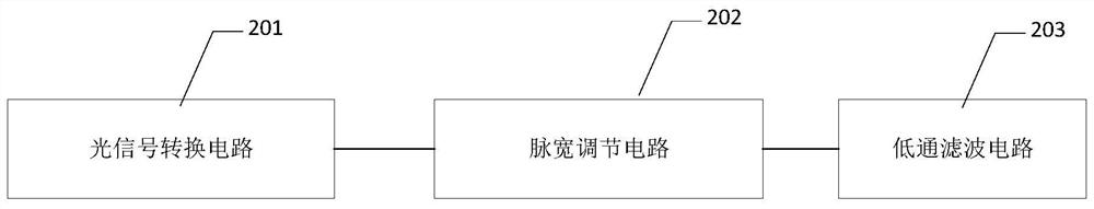
[0049] Such as Figure 4 Shown is an electrical schematic diagram of the optical signal processing module disclosed in the embodiment of the present invention. For those skilled in the art, this figure is only one embodiment of the present invention, and the solution of the present invention is not limited thereto.

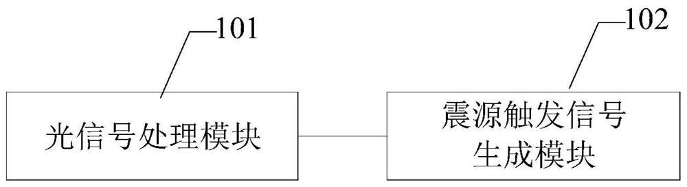
[0050] In this embodiment, the optical signal processing module disclosed in the embodiment of the invention includes: an optical signal conversion circuit 401 , a pulse width adjustment circuit 402 , and a low-pass filter circuit 403 .

[0051] Wherein, the optical signal conversion circuit 401 includes: a fiber optic receiver X1, an optocoupler U1, and a current limiting resistor R1, and the optical signal conversion circuit 401 is externally connected to a 9V battery (VCC3).

[0052] After receiving the optical signal excited by the electric spark source, the optical fiber receiver X1 converts the signal into a 9V electrical signal through the current limiting...


PUM


Abstract

The invention provides an electric spark source triggering device and a control method. The electric spark source triggering device comprises an optical signal processing module and a seismic source trigger data generation module; the optical signal processing module is used for converting the received optical signal excited by an electric spark source into a voltage control signal; and the seismic source trigger signal generation module is used for obtaining the current time according to the voltage control signal to generate an electric spark seismic source trigger signal. The voltage control signal is directly generated according to the optical signal generated by excitation of the electric spark source to generate the trigger data, so that the excitation time of the electric spark source is accurately controlled, the delay precision of triggering of the electric spark source is improved, and the acquisition precision is ensured.

Description

technical field [0001] The present invention relates to geophysical prospecting technology, in particular to geophysical prospecting acquisition technology, specifically an electric spark seismic source triggering device and a control method. Background technique [0002] With the wide application of the green source EDM source, the requirement for synchronous triggering accuracy with the acquisition host signal is getting higher and higher, and the unstable trigger delay directly affects the signal acquisition quality. [0003] Synchronous triggers in the prior art often adopt inductive and vibration types. In practical applications, due to the different excitation environments of electric spark sources, the inductive synchronizer has the problem of unstable trigger delay, and the delay time fluctuates within 0-3ms, which cannot meet the requirements of VSP logging (vetical seismic profile, vertical seismic profile). ), cross-hole CT and other applications requiring high-p...

Claims


Application Information

Patent Timeline
Patent Type & Authority Applications(China)
IPC IPC(8): G01V1/157
CPCG01V1/157
Inventor 黄元溢蒋辉张建军孟凡厚王雪峰
Owner BC P INC CHINA NAT PETROLEUM CORP
Why Eureka
Try Eureka