Digital DLL device, digital DLL control method, and digital DLL control program
a digital dll and control method technology, applied in the direction of digital storage, pulse automatic control, instruments, etc., to achieve the effect of reducing errors
- Summary
- Abstract
- Description
- Claims
- Application Information
AI Technical Summary
Benefits of technology
Problems solved by technology
Method used
Image
Examples
embodiment 1
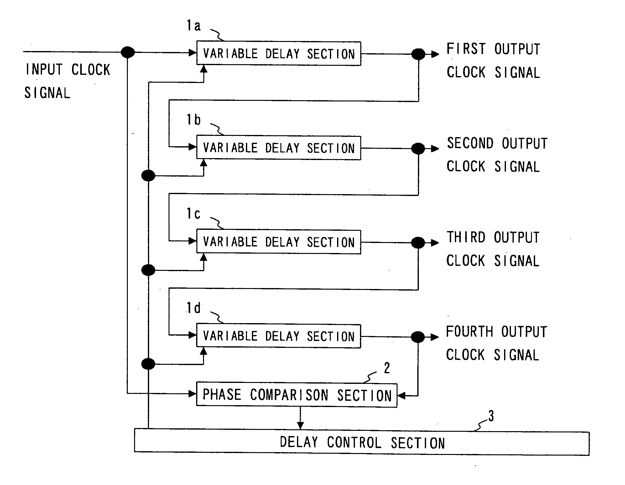
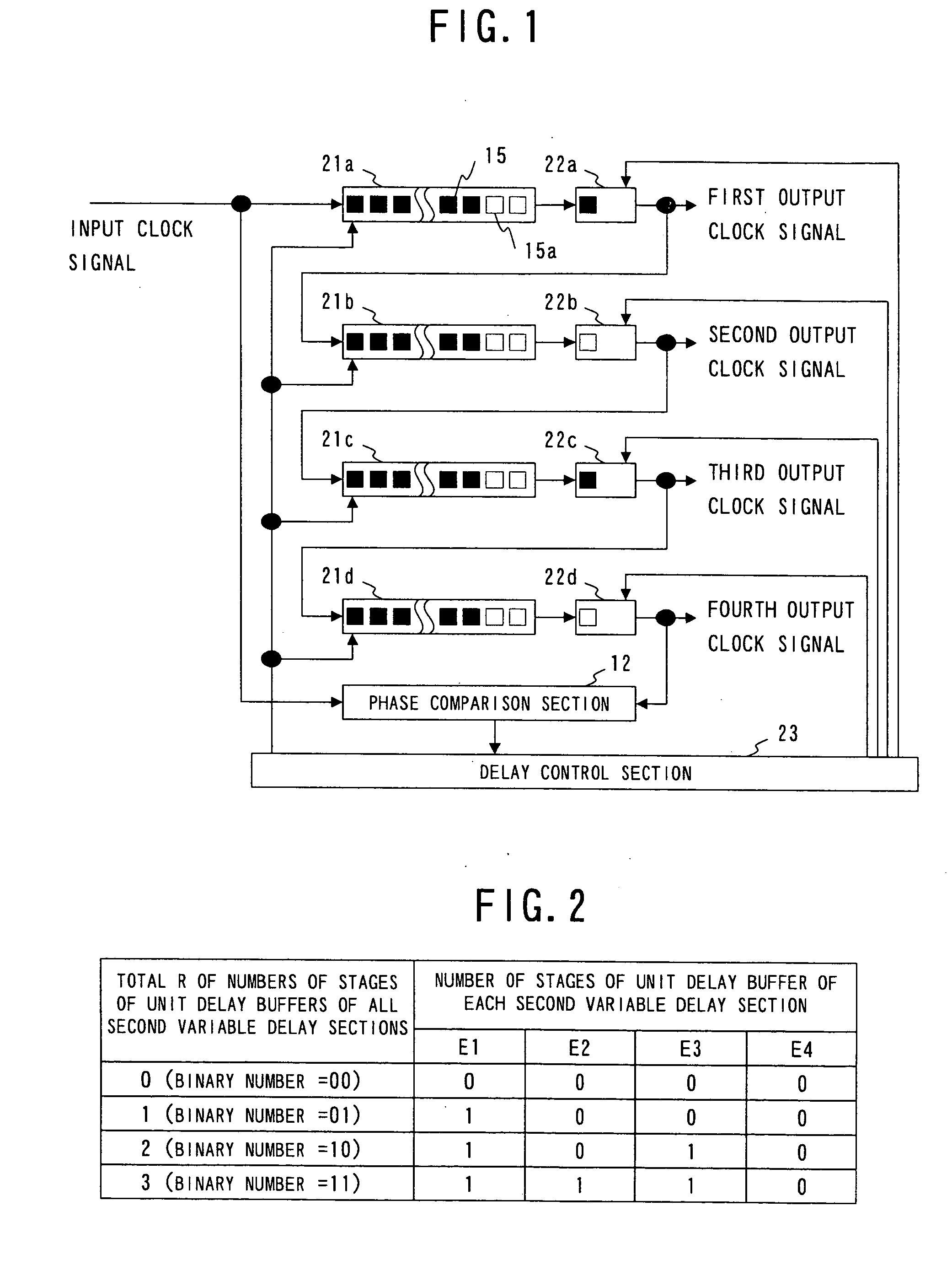
[0039] First of all, reference will be made to the construction of a digital DLL device according to a first embodiment of the present invention. FIG. 1 is a block diagram that shows one example of the construction of the digital DLL device according to the first embodiment. In FIG. 1, the same symbols as those in FIG. 7 designate the same or corresponding parts as those shown in FIG. 7, and an explanation thereof is omitted here. In this first embodiment, a delay control section 23 is provided instead of the delay control section 13 in FIG. 7. In addition, a first variable delay section 21a and a second variable delay section 22a are provided instead of the first variable delay section 11a; a first variable delay section 21b and a second variable delay section 22b are provided instead of the first variable delay section 11b; a first variable delay section 21c and a second variable delay section 22c are provided instead of the first variable delay section 11c; and a first variable d...
embodiment 2
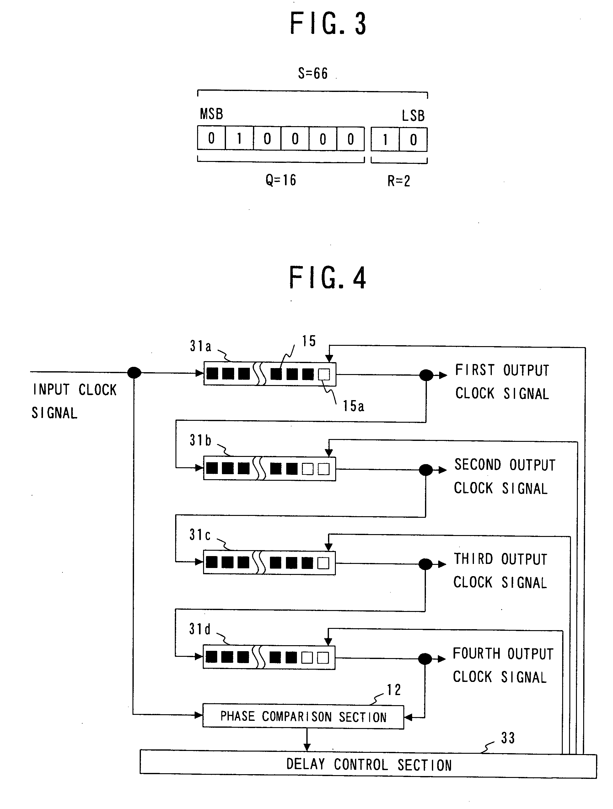
[0049] A second embodiment of the present invention is provided with only variable delay sections 31a, 31b, 31c, 31d that can control the number of stages of individual unit buffers, as in the second variable delay sections 22a, 22b, 22c, 22d of the above-mentioned first embodiment.
[0050] First, reference will be made to the construction of a digital DLL device according to the second embodiment of the present invention. FIG. 4 is a block diagram that shows one example of the construction of the digital DLL device according to the second embodiment. In FIG. 4, the same symbols as those in FIG. 7 designate the same or corresponding parts as those shown in FIG. 7, and an explanation thereof is omitted here. In this second embodiment, a delay control section 33 is provided instead of the delay control section 13 in FIG. 7. In addition, a variable delay section 31a is provided instead of the first variable delay section 11a; a variable delay section 31b is provided instead of the first...
PUM
 Abstract
Description
Claims
Application Information
 - R&D
- Intellectual Property
- Life Sciences
- Materials
- Tech Scout
- Unparalleled Data Quality
- Higher Quality Content
- 60% Fewer Hallucinations
Browse by: Latest US Patents, China's latest patents, Technical Efficacy Thesaurus, Application Domain, Technology Topic, Popular Technical Reports.
© 2025 PatSnap. All rights reserved.Legal|Privacy policy|Modern Slavery Act Transparency Statement|Sitemap|About US| Contact US: help@patsnap.com


