
Air filter with peculiar smell eliminating function

An air filter and functional technology, applied in the fields of dispersed particle filtration, chemical instruments and methods, dispersed particle separation, etc., can solve the problems of outer layer pollutants falling off, secondary pollution, and covering pollutants on the surface of the filter screen.

Inactive Publication Date: 2021-06-04
阜阳不平凡美容护肤有限公司
View PDF0 Cites 1 Cited by
  • Summary
  • Abstract
  • Description
  • Claims
  • Application Information

AI Technical Summary

Problems solved by technology

[0003] Aiming at the deficiencies in the prior art, the purpose of the present invention is to provide an air filter with the function of eliminating peculiar smell, so that under long-term use, the pollutants on the surface of the filter screen will continue to increase with the passage of time, thereby The surface of the filter is covered with pollutants, causing the outer layer of pollutants to slowly fall off to the inside of the device. When the device is used next time, the pollutants inside the device will flow out with the gas, causing secondary pollution.

Method used


Image

  • Air filter with peculiar smell eliminating function
  • Air filter with peculiar smell eliminating function
  • Air filter with peculiar smell eliminating function

Examples


Embodiment 1

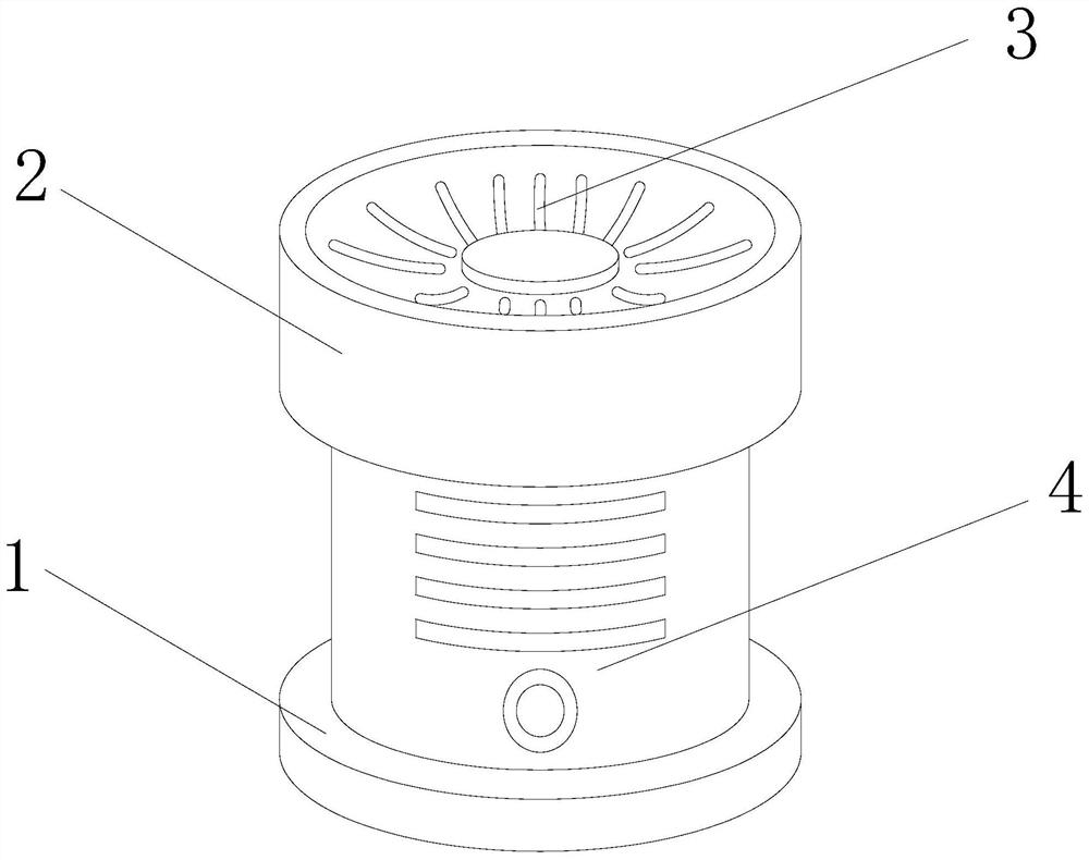
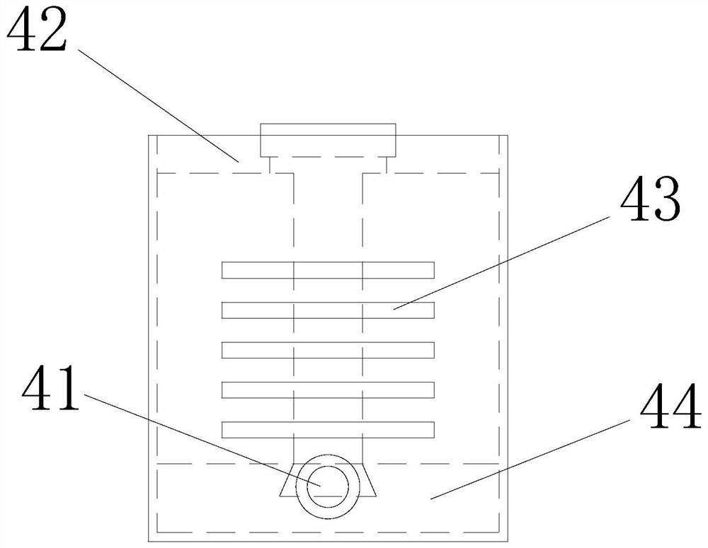
[0025] as attached figure 1 to attach Figure 5 Shown:

[0026] The present invention provides an air filter with the function of eliminating peculiar smell. Its structure includes: a base 1, an upper cover 2, an air outlet 3, and a body 4. The inner ring of the cover 2 is nested in the outer ring of the fuselage 4, and the air outlet 3 and the upper cover 2 are an integrated structure;

[0027] The fuselage 4 includes a switch 41, a housing 42, an air inlet 43, and a collection device 44. The switch 41 is installed on the outside of the housing 42, and the front of the housing 42 is provided with an air inlet 43. The collection device 44 The outer ring of the housing 42 is nested in the inner ring.

[0028] Wherein, the housing 42 includes a scraping device a1, a fan a2, a rotating shaft a3, a filter rod a4, and a driver a5, the scraping device a1 is attached to the filter rod a4, and the fan a2 is installed on the On the inner side, the rotating shaft a3 runs through th...

Embodiment 2

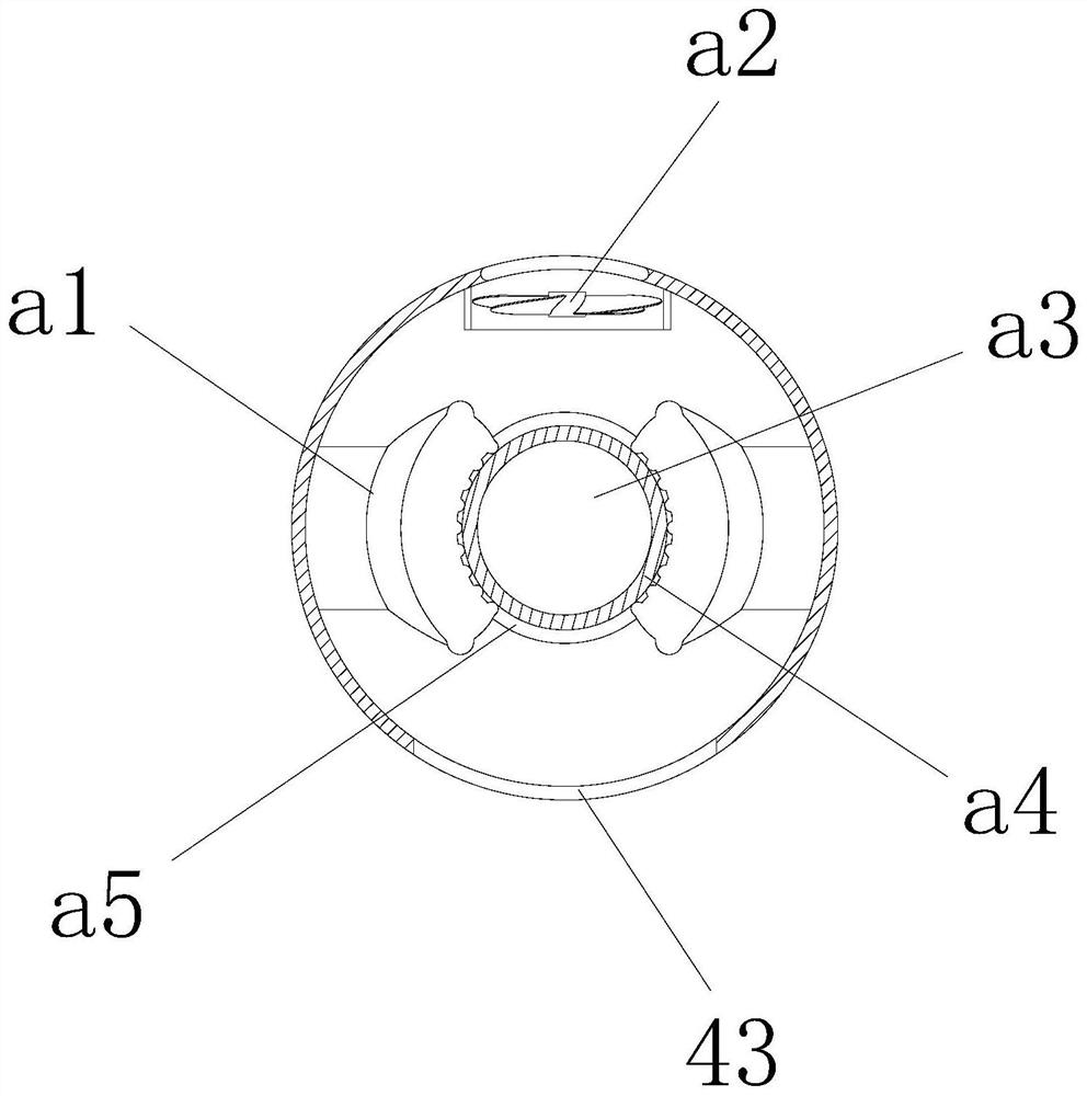
[0034] as attached image 3 As shown: the housing 42 includes a scraping device a1, a fan a2, a rotating shaft a3, a filter rod a4, and a driver a5. The scraping device a1 is attached to the filter rod a4, and the fan a2 is installed in the housing 42 The inner side of the rotating shaft a3 runs through the filter rod a4, the inner ring of the driver a5 is nested with the outer ring of the rotating shaft a3, and the scraping device a1 is symmetrically distributed on both sides of the filter rod a4, which can improve the filter rod The scrape-off effect on the surface of a4.

[0035] as attached Figure 6 to attach Figure 8 Shown:

[0036] The present invention provides an air filter with the function of eliminating peculiar smell. The collection device 44 includes a collection box 441, a rotating device 442, and a support rod 443. The inner side of the collection box 441 is fixedly connected to the bottom end of the support rod 443. , the rotating device 442 is slidingly ...


PUM


Abstract

The invention provides an air filter with a peculiar smell eliminating function, which structurally comprises a base, an upper cover, an air outlet and a machine body, wherein the base and the machine body are of an integrated structure, an inner ring of the upper cover is nested in an outer ring of the machine body, and the air outlet and the upper cover are of an integrated structure.When a switch is started, the equipment starts to operate, a driver starts to rotate, a rotating shaft drives a filter stick to rotate, scraping devices located on the two sides of the filter stick can scrape pollutants on the surface of the filter stick, meanwhile, under the action of a draught fan, airflow enters a sleeve through a through hole, the induced draft fan is enabled to rotate, and then the pollutants scraped by a steel wire ball are absorbed, so that the phenomenon that pollutants are always accumulated on the surface of the filter stick along with time to cause secondary pollution is avoided. Meanwhile, in the moving and scraping process, part of the pollutants fall above the collecting device, and the pollutants can be further collected through overturning of a baffle.

Description

technical field [0001] The invention relates to the field of deodorizing air, in particular to an air filter with the function of deodorizing. Background technique [0002] With the continuous development of society, people's living standards are gradually improving, but the smog is getting more and more serious. In order to purify the air, most people use air filters to absorb, decompose or transform the smog particles in the air. And eliminate peculiar smell simultaneously, can provide clean and safe air to user, so have the air filter of eliminating peculiar smell function to be used widely, but have the air filter of eliminating peculiar smell function in the prior art, in When in use, the pollutants enter the filter with the gas, making the pollutants filtered on the filter, and the pollutants will be adsorbed on the surface of the filter. After a long time of use, the pollutants on the surface of the filter will be As time goes by, the pollutants will be covered on th...

Claims


Application Information

Patent Timeline
IPC IPC(8): B01D46/26B01D46/00B01D46/24B01D46/48
CPCB01D46/26B01D46/2411B01D46/48B01D46/681
Inventor 李珍
Owner 阜阳不平凡美容护肤有限公司
Learn More