Metal window frame with cleaning device

A technology for cleaning device and window frame, applied in the direction of window/door frame, window/door, cleaning equipment, etc., can solve problems such as difficulty in cleaning the exterior of glass windows, poor appearance of windows, affecting indoor lighting effects, etc.

Pending Publication Date: 2021-06-08
上海知此电子有限公司
View PDF0 Cites 0 Cited by
  • Summary
  • Abstract
  • Description
  • Claims
  • Application Information

AI Technical Summary

Problems solved by technology

Therefore, after the existing metal window frame is used, it is difficult to clean the glass wi...

Method used


Image

  • Metal window frame with cleaning device
  • Metal window frame with cleaning device
  • Metal window frame with cleaning device

Examples


Embodiment 1

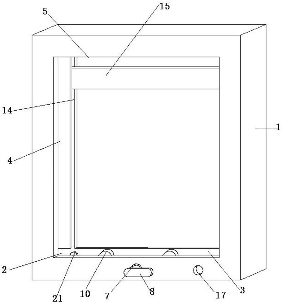
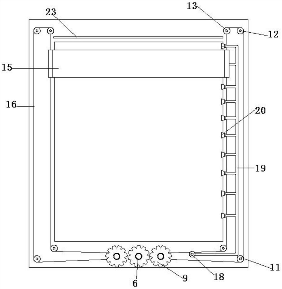
[0016] Such as figure 1 and figure 2 A metal window frame with a cleaning device is shown, which includes a window frame body 1, and the inside of the window frame body 1 is provided with an installation groove 2, and the installation groove 2 includes a bottom groove 3, a side groove 4 and a top groove 5, The bottom groove 3, the side groove 4 and the top groove 5 are connected, and the bottom groove 3 is provided with a driving gear 6, and the driving gear 6 is installed on the rotating shaft, and the end of the rotating shaft is fixed by a two-way damping bearing 7 On the window frame body 1, the rotating shaft is connected with the handle 8, and the handle 8 is located outside the bottom groove 3, and driven gears 9 are provided on both sides of the driving gear 6, and can be meshed with it for transmission. The driven gear 9 is located inside the bottom groove 3. One end of the driven gear 9 is connected to the window frame body 1 through a bearing, and the other end is...

Embodiment 2

[0018] Such as Figure 1-Figure 3 A metal window frame with a cleaning device is shown, which includes a window frame body 1, and the inside of the window frame body 1 is provided with an installation groove 2, and the installation groove 2 includes a bottom groove 3, a side groove 4 and a top groove 5, The bottom groove 3, the side groove 4 and the top groove 5 are connected, and the bottom groove 3 is provided with a driving gear 6, and the driving gear 6 is installed on the rotating shaft, and the end of the rotating shaft is fixed by a two-way damping bearing 7 On the window frame body 1, the rotating shaft is connected with the handle 8, and the handle 8 is located outside the bottom groove 3, and driven gears 9 are provided on both sides of the driving gear 6, and can be meshed with it for transmission. The driven gear 9 is located inside the bottom groove 3. One end of the driven gear 9 is connected to the window frame body 1 through a bearing, and the other end is conn...


PUM


Abstract

The invention discloses a metal window frame with a cleaning device. The metal window frame comprises a window frame body, a mounting groove is formed in the inner side of the window frame body, a driving gear is arranged in a bottom groove, the driving gear is fixed to the window frame body in the mode that a rotating shaft is matched with a bidirectional damping bearing, the rotating shaft is connected with a handle, and the two sides of the driving gear meshes with driven gears. The driven gears are connected with the window frame body after being connected with a winding roller, a lower transmission pulley is arranged on the outer sides of the driven gears, an upper transmission pulley is arranged above the lower transmission pulley, a tensioning pulley is arranged on the inner side of the upper transmission pulley, sliding ways are mounted in edge grooves in the two sides, the end parts of rubber strips are mounted in the sliding ways, the top ends of the end parts of the rubber strips are connected with one end of a steel wire, the other end of the steel wire is connected with the lower ends of the end of the rubber strips after being tensioned through a tensioning pulley and the like, and a water inlet is formed in the bottom end of the window frame body and connected with a water spraying mechanism through a water inlet connector. A traditional window structure does not need to be changed, and only the window frame needs to be replaced.

Description

technical field [0001] The invention relates to the technical field of window frames, in particular to a metal window frame with a cleaning device. Background technique [0002] Metal window frames are widely used in the installation of glass windows in buildings because of their sturdiness and other characteristics. In order to improve space utilization, existing buildings mostly adopt multi-layer structure. Therefore, after the existing metal window frame is used, it is difficult to clean the glass window externally, resulting in a poor appearance of the window and affecting the indoor lighting effect. Contents of the invention [0003] The object of the present invention is to provide a metal window frame with a cleaning device to solve the problems mentioned in the background art. In order to achieve the above object, the present invention provides the following technical solutions: a metal window frame with a cleaning device, including a window frame body, the inner...

Claims


Application Information

Patent Timeline
IPC IPC(8): E06B1/12E06B1/36E06B7/28A47L1/02
CPCA47L1/02E06B1/12E06B1/36E06B7/28
Inventor 郝阿明孙斌李杰毛峰
Owner 上海知此电子有限公司
Why Eureka
Try Eureka