Joint connecting structure of robot and robot

A connection structure and robot technology, applied in the direction of joints, manipulators, program-controlled manipulators, etc., can solve problems such as general flexibility, and achieve the effects of good transmission stability, high bionics, and high flexibility

Active Publication Date: 2021-06-18
FOSHAN ZHIANG TECH CO LTD
View PDF9 Cites 0 Cited by
  • Summary
  • Abstract
  • Description
  • Claims
  • Application Information

AI Technical Summary

Problems solved by technology

[0003] The flexibility of the current robot joint structure is average, therefore, it is necessary to improve

Method used


Image

  • Joint connecting structure of robot and robot
  • Joint connecting structure of robot and robot
  • Joint connecting structure of robot and robot

Examples


Embodiment 1

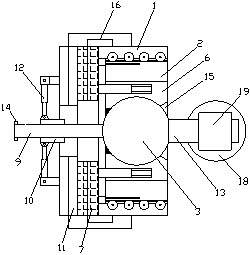
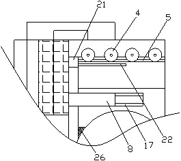
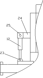
[0033] Such as Figure 1-4As shown, a joint connection structure of a robot includes an outer ring body 1, a rotating bearing 2, and a joint sphere 3, and a guide wheel 4 is provided in the outer ring 4, and the guide wheel 4 is rotated to the outer ring 1 The guide groove 5 facing the guide wheel 4 is provided on the outer ring of the rotating bearing 2, the guide wheel 4 inserted into the guide groove 5, the outer ring of the rotating bearing 2 through the guide groove 5 and the guide wheel 4 Slide with the outer ring 1, the inner ring of the rotating bearing 2 is fixedly provided with a retaining ring body 6, and the inner ring surface of the retaining ring 6 is formed with a limit slot corresponding to the joint sphere 3 (not The joint ball body 3 is attached to the limit slot, the joint ball body 3 is attached to the retaining ring 6 through the limit slot and positioned in the retaining ring 6, and the rotating bearing 2 is provided for The first electric turntable 7 that dri...

Embodiment 2

[0039] Such as Figure 1-5 As shown, a joint connection structure of a robot includes an outer ring body 1, a rotating bearing 2, and a joint sphere 3, and a guide wheel 4 is provided in the outer ring 4, and the guide wheel 4 is rotated to the outer ring 1 The guide groove 5 facing the guide wheel 4 is provided on the outer ring of the rotating bearing 2, the guide wheel 4 inserted into the guide groove 5, the outer ring of the rotating bearing 2 through the guide groove 5 and the guide wheel 4 Slide with the outer ring 1, the inner ring of the rotating bearing 2 is fixedly provided with a retaining ring body 6, and the inner ring surface of the retaining ring 6 is formed with a limit slot corresponding to the joint sphere 3 (not The joint ball body 3 is attached to the limit slot, the joint ball body 3 is attached to the retaining ring 6 through the limit slot and positioned in the retaining ring 6, and the rotating bearing 2 is provided for The first electric turntable 7 that dr...


PUM


Abstract

The invention discloses a joint connecting structure of a robot and the robot. The joint connecting structure of the robot comprises an outer ring body, a rotating bearing and a joint sphere, a guide wheel is arranged in the outer ring body, a guide groove matched with the guide wheel is formed in an outer ring of the rotating bearing, a retaining ring body is fixedly arranged on an inner ring of the rotating bearing, a limiting groove matched with the joint sphere is formed in the inner ring face of the retaining ring body, a first electric rotating disc used for driving the rotating bearing to rotate is arranged on the back face of the rotating bearing, a first electric telescopic rod used for driving the retaining ring body to stretch out is arranged on the movable face of the first electric rotating disc, a connecting rod is arranged on the joint sphere, a linear bearing is arranged on the connecting rod, a second electric rotating disc is arranged on the back face of the first electric rotating disc, and a second electric telescopic rod is arranged on the movable surface of the second electric rotating disc. The joint connecting structure of the robot is excellent in flexibility.

Description

Technical field [0001] The present invention relates to a joint connection structure of a robot and a robot. Background technique [0002] The robot is a machine device that automatically performs work, which can accept human commands, but also to run a pre-arranged program, or according to the principles of manual intelligence technology, its task is to assist or replace human work, such as Produces, construction, or dangerous work. [0003] The current flexibility of robot joint structure is general, so it is necessary to improve. Inventive content [0004] The technical problem to be solved by the present invention is to provide a flexible artifact joint connection structure and robot. [0005] In order to solve the above problems, the present invention adopts the following technical solutions: [0006] A robot's joint connecting structure includes an outer ring body, a rotating bearing, and a joint sphere, the outer ring disposed with a guide wheel and an outer ring, and the...

Claims


Application Information

Patent Timeline
Patent Type & Authority Applications(China)
IPC IPC(8): B25J17/02B25J9/00
CPCB25J9/0009B25J17/02B25J17/0275
Inventor 黄楠铭蔡雪芝许东伟黄国静刘智楷
Owner FOSHAN ZHIANG TECH CO LTD
Why Eureka
Try Eureka